This instruction manual is intended to be a guide when operating the 112 Extreme Seam. To ensure optimal performance from your welder, please follow the recommendations and specifications precisely.
Table of Contents
- Chapter 1: Intended Use
- Chapter 2: Explanation of Warnings
- Chapter 3: Electrical and Air Requirements
- Chapter 4: Principles of Heat Sealing
- Chapter 5: Screen Shots
- Chapter 6: Adjustments
- Chapter 7: Maintenance
- Chapter 8: Welding Tips
- Chapter 9: Additional Machine Documents
For more technical information regarding this machine call our Resolution Center at 1-855-888-WELD or email service@weldmaster.com.
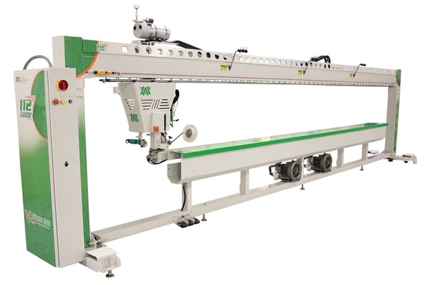
1.0 Intended Use
The 112 is a rotary hot air welding machine intended to heat-seal weldable thermal plastics such as:
- Non-woven polypropylene
- Vinyl (PVC) laminated fabrics
- Vinyl (PVC) coated fabrics
- Vinyl (PVC) films
- Polyurethane (PU) coated fabrics
- Polyurethane (PU) films
- Polypropylene (PP) coated fabrics
- Polyethylene (PE)
- Thermoplastic Rubber (TPR) film
- Thermoplastic Rubber (TPR) fabrics
- Rigid Extruded Products
The manufacturer does not approve of:
- Any other uses for these machines.
- The removal of any safety guards while in operation.
- Unauthorized modification of the machines.
- Using replacement parts that are not manufacturer-approved.
 Only a properly-trained technician may operate and/or perform any routine maintenance orrepairs to the machines.
NOTE: The manufacturer will not be held liable for any damage or injuries occurring from any inappropriate use of this machine.
2.0 Explanation of Warnings
There are several different warning symbols placed on the Miller Weldmaster 112. The symbols are to alert the operator of potentially hazardous areas on the machine. Familiarize yourself with their placement and meaning.
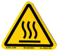
Caution: Hot
The “Caution: Hot” symbol is placed on a guard nearhot surfaces.

Danger: Pinch Points
The “Danger: Pinch Points” symbol is placed near any potential pinch points. Do not place any body parts near these sections of the machine while the machine is running.
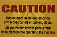
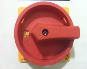
Caution: Unplug Machine
The “Caution: Unplug Machine” sticker is placed near the opening of the cabinet and all access panels. To prevent electrocution, the machine should always have the power disconnected before the cabinet door is open.

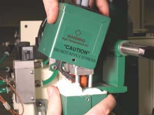
Warning: Keep Hands Clear
The“Warning: Keep Hands Clear” sticker is placed on the Heater Assembly. To prevent any pinching or burns, be aware of the location of your hands at all times.

Warning: High Temperature Air
The “Warning: High Temperature Air” sticker is placed on the Heater Assembly.

Caution: Electricity
The “Caution: Electricity” sticker is placed near areas that contain electrical.
3.0 Electrical and Air Requirements
Warning! Only a qualified electrician may connect the electrical power.
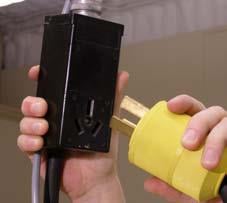
Electrical Supply
Due to the number of different style outlets available, the cord will not be included. It is recommended that your electrician install a cord and plug that is comparable to your style power outlet. You may choose to have your power cord hard-wired into your Power Supply. It is recommended that your electrician use a Junction Box with an ON/OFF switch with short circuit protection as required by local electrical code to be suitable for the primary disconnect. The Miller Weldmaster 112 Extreme requires one of the following power supplies. Please reference the electrical schematic for which power supply your machine requires.
- 80 Amperes - Single phase - 230 Volts
- 80 Amperes - 3 phases - 230 Volts
- 60 Amperes - 3 phases - 400 Volts
Shop Air Supply
The Miller Weldmaster 112 Extreme includes an In-Shop Air Supply Valve that allows quick connects and disconnects to your shop air supply. Due to the number of different style airline connectors, a male quick-connect is not included. You will want to select a male quick-connect with a ¼ inch NPT (National Pipe Thread) to match your female quick-connect. The Miller Weldmaster 112 Extreme requires the following shop air requirements:
- Minimum of 12 cfm at 120 psi
- Not to exceed 340 liters/min at 8.2 Bar
- An in-line water and dirt separator
Safety notes
Do not adjust the material while the machine is moving. Keep hands, long hair, loose clothing, and articles such as neckties away from the rollers have pinch points rollers to avoid entanglement and entrapment that can trap body parts or clothing and cause serious injury. Provide enough space around machine to ensure the safe and effective operation. The machine must be motionless and moving parts blocked before any cleaning, oiling, adjusting, repairing or maintaining work is done on any repairing or maintaining work is done on any part of the machine. Always wear Personal protective equipment. (PPE) refers to protective clothing, helmets, goggles, or other garment designed to protect the wearer’s body from injury.
4.0 Principals of Heat Sealing
Hot Air
The heat required for the welding operation is created electrically by two heating element located inside the heat element housing. The hot air temperature ranges from 100 to 1350 Degrees Fahrenheit or 25 to 730 Degrees Celsius.
Speed
The Speed of the Weld Rollers determines the amount of time the heat is applied to the material being welded. The slower the speed setting, the more the material will be heated. The faster the speed setting, the less the material will be heated. To achieve the best weld, a minimal amount of heat should be applied to the material while still achieving a full weld. Too much heat will cause distortion of the material; while not enough heat will prevent the material from welding.
Pressure
The pressure of the weld roller is the final step when creating a weld. The pressure of the weld roller compresses the heated material together completing the welding process.
Summary
When heat sealing, the correct combination of heat, speed, and pressure will allow you to achieve a properly welded seam.
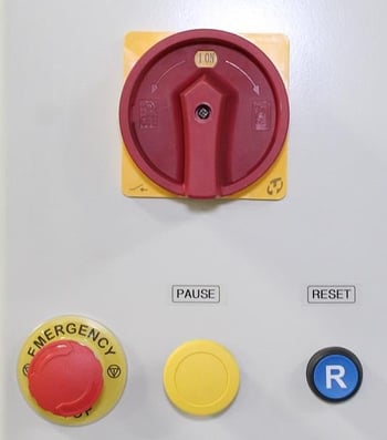
Emergency Stop: Pressing this button will shut down the machine and the button will need to be twisted and pulled out to start the machine again.
Pause: Pressing this button stops the head carriage from traveling.
Reset: Pressing this button will activate the machine on start up or after an emergency stop is pressed.
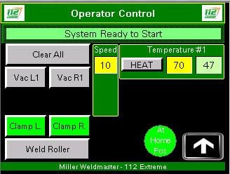
Clear All: The purpose of this is to give a simpler means to turn off all vacuums and fabric clamps by touching one button.
Vacuum Left: The purpose of this function is to turn on or off the left vacuum.
Vacuum Right: The purpose of this function is to turn on or off the right vacuum.
Clamp Left: The purpose of this function is to open or close the left clamp.
Clamp Right: The purpose of this function is to open or close the right clamp.
Weld Roller: The purpose of this function is to lift the weld roller up or down.
Machine Speed: The purpose of Machine Speed is to control the speed of the carriage assembly during the welding process. The machine speed number is a percentage of how fast the 112 extreme head carriage will run.
Heat: The purpose of this function is to turn on and off the heat.
Temperature SP: The purpose of this box is to show the set point for the temperature and also allow the operator to manually change the temperature without going into the recipes.
Temperature PV: The purpose of this box is to show the operator what the actual temperature is reading at the elements.
Arrow Button: Used to access the controls pop-up panel.
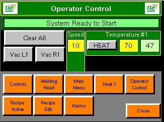
Control: Pressing this button opens the Control screen.
Welding Head: Pressing this button opens the welding head screen.
Main Menu: Pressing this button opens the main menu screen.
Heat 1: Pressing this button, opens up the controls for each welding head.
Recipe Active Screen: Displays all the current parameters for the selected recipe.
Recipe Edit: Pressing this button opens up the Recipe Edit screen.
Alarm: This displays the current active alarms if any.
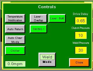
Temperature Notification: When this is selected, the 112 Extreme will notify the operator to check nozzle placement when the temperature controller is changed+/- 160 F.
Auto Return: When this is selected, it will turn green and the carriage will return on its own when the end position is reached.
Auto Clear Mode: When this is selected, it will turn green and at the end of a run, when using end position, the vacuums and fabric clamp will turn off.
Chiller: Turns the weld roller chillers on and off.
Laser-Overlap: The purpose of this button is when depressed, it will turn green and turn on the overlap laser and turn off the butt laser.
Laser-Butt: The purpose of this button is when depressed, it will turn green and turn on the butt laser and turn off the overlap laser.
Weld/Cut: In this box, if weld is showing, the 112 extreme is in the weld mode. By touching the box it will switch the mode to cut and the 112 will be in the cut mode.
Swing: When this is selected, it will turn green and the nozzle will swing in. If Swing is not selected, the nozzle will not swing in when the start button is pressed.
Drive Delay: The purpose of the drive delay is to stall the weld roller temporally and allow the hot air nozzle to swing into place. If the drive delay is set to high, it will cause the material to burn at the start. If the drive delay is set to low, it will leave a spot not welded at the start.
Clutch Pressure: The purpose of clutch pressure is to vary the amount of drive force on the weld roller. This helps eliminate any wrinkling of material. Increasing the clutch pressure will allow the weld roller to spin faster in relation to the head carriage speed. Decreasing the clutch pressure will spin the weld roller slower than the head carriage.
Weld Pressure: The purpose of Weld Pressure is to vary the amount of pneumatic pressure between the weld roller and the welding track.
Mode: This will switch between weld and cut.
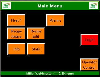
Heat 1: Pressing this button, opens up the controls for the selected welding head.
Alarms: This displays the current active alarms if any.
Recipe Active screen: Displays all the current parameters for the selected recipe.
Recipe Edit: Pressing this button opens up the Recipe Edit screen.
Info: Pressing this button will take you to the information screen.
Stats: Pressing this will take you to the stats screen.
Operator Control Screen: This is the main screen the operator will use. This is the screen the machine will start up to.
Login: The Maintenance Configuration button will take the operator to the Maintenance Configuration screen. To enter this screen, the operator will be prompted to enter a user name and password. User name: TECH Password: 1234. This screen will take the operator to a screen similar to the Operator Configuration screen. The difference is that the Maintenance Configuration screen will allow the operator to tune the temperature controller, change language and adjust cutter and return run speed.
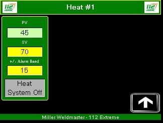
Temperature SP: The purpose of this box is to show the set point for the temperature and also allow the operator to manually change the temperature without going into the recipes.
Temperature PV: The purpose of this box is to show the operator what the actual temperature is reading at the elements.
Alarm Band: Is a number that can be set by the operator by touching and if the temperature changes +/- the setting a warning will be displayed on the screen.
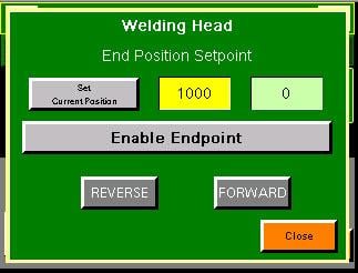
Set Current Position: This will set the point of how far the welding head will travel.
Set Point: This is distance the welding head will travel.
Actual: This is the position the head is currently.
Enable Endpoint: With this turned on it will enable the welding head end point.
Reverse: Jogs the welding head in reverse.
Forward: Jogs the welding head forward.
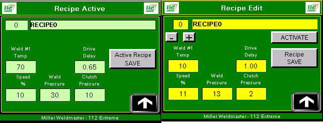
Recipe #: The number of the current recipe.
Recipe Name: The name of the current recipe.
Weld Unit #: This is the temperature set point we are setting each welding head at.
Speed %: Controls the overall machine speed. This is the master speed control.
Clutch Pressure: The purpose of Clutch Pressure is to vary the amount of drive force on the weld roller.
Weld Pressure: The purpose of Weld Pressure is to vary the amount of pneumatic pressure between the weld roller and the welding track.
Drive Delay: Is the amount of time between the start of your welding head, and the nozzles to swing in before the welding head will start.
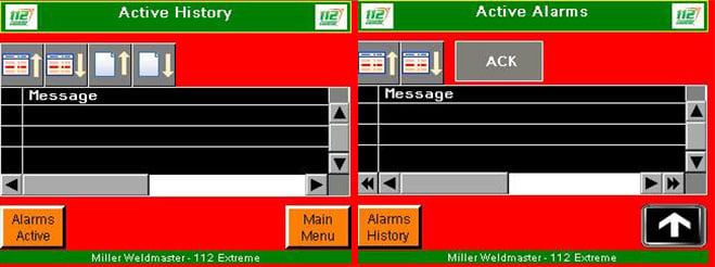
Alarm Active Screen: This displays the current active alarms if any.
Ack: This button is used to acknowledge any active alarms.
Alarm History: This is used to pull up any and all old alarms ever present on the machine.
6.0 Adjustments
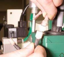
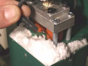
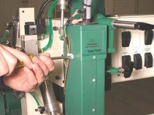
Nozzle Adjustment
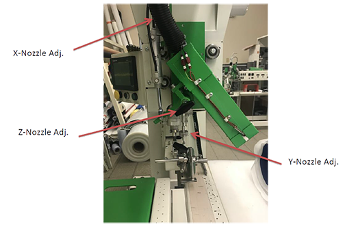
Nozzle placement is a key component in heat sealing. A properly-placed nozzle will be centered on the weld roller approximately ¼-inch away and have a slight whistle during the welding process. When an adjustment is needed, turn the speed control to a low setting. Make the adjustment and check the nozzle placement by engaging the Start Switch. Remember that the nozzle placement will change when welding at different temperatures. Check the placement when the temperature is changed more than 160 degrees C.
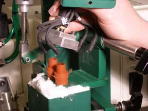
1. X Nozzle Adjustment - The X Nozzle
Adjustment allows left and right fine-tuning of the Hot Air Nozzle. The proper X-Nozzle Adjustment will leave the Hot Air Nozzle centered on the Weld Roller.
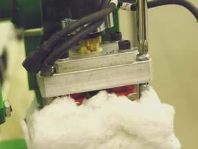
2. Y Nozzle Adjustment - The Y Nozzle
Adjustment allows up and down fine-tuning of the Hot Air Nozzle. The proper Y-Nozzle Adjustment will leave the Hot Air Nozzle directed at the pinch point of the Weld Roller and the Welding Track. A whistling sound should be heard as the air from the nozzle hits this pinch point.
3. Z Nozzle Adjustment - The Z Nozzle
Adjustment allows in and out fine-tuning of the Hot Air Nozzle. The proper Z-Nozzle Ad justment will leave the Hot Air Nozzle approximately ¼ to ½ inch away from the pinch point.
4. Nozzle Adjustment Finished
When finished, the Hot Air Nozzle should be placed in the center of the weld roller left to right, 1/4 to 1/2 inch from the pinch point of the weld roller and track.
 Warning! When adjusting the lasers, do not look directly into the laser source. Use caution when calibrating lasers.
Laser Alignment
Double Laser Line
1.Turn the POWER on.
2. Leave the Heat Switch in the OFF position. Load some sample fabric (white is best) under the fabric clamp and extend to the end of the machine.
3. Turn the Left and Right Vacuums ON.
4. Engage the Weld Roller to the DOWN position and align the inside edge of the weld roller to the edge of the first row of vacuum hole on the vacuum welding track.
5. Turn the Speed Control to a speed of 20.
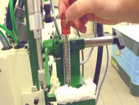
6. Using a ballpoint pen, place it on the inside edge of the Weld Roller, where the laser should be. Repeat for outside laser line.
7. Depress the START button and edge the roller the length of the welding track.
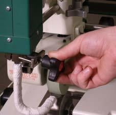
8. If needed, make the first adjustment by loosening the laser mount knob to calibrate the laser in and out to the drawn line. When satisfied, tighten the laser mount knob.
9. If needed, make the second adjustment by loosening the laser mount knob and calibrate the laser by turning the top of it. This will rotate the laser line. When satisfied, tighten the laser mount knob.
Butt Seam
1. Flip the Laser Switch to the Butt Seam mode.
2. Move the Weld Roller over so that the edge is against the laser, considering the double laser line has been adjusted properly and the fabric with pen lines remain in place. Measure to the middle point of the double laser making a mark at this point. Move the edge of the weld roller to this mark and tighten. Follow step seven of the above. Align laser.
Guide Adjustments
Welding a Hem: The hem guide needs to be 1/16 to 1/8inch off track and aligned perpendicular to track. The outside of guide needs to be adjusted to outside of weld roller. After running a test if there is a pocket on the hem move guide away from operator.
- Set machine to the desired settings, install your hemming guide to the machine.
- Align the hemming guide so the outside edge is aligned with the edge of the weld roller.
- Generally the clutch pressure needs to be adjusted to a higher setting when welding a hem.
- Do not pull the fabric sideways when feeding the fabric into the hemming guide, roll the fabric into the guide. If you pull the fabric sideways it will become tight and bind up in the guide.
1. Install hem guide.
2. Slide edge of material through guide pinching material on top of itself.
3. Making sure it is square with the edge.
4. While pinching, slide material under weld roller.
5. Put weld roller down than put clamp down.
6. Pull material tight, make sure the material between the wheel and guide is tight so that the nozzle will swing in free.
7. Press start and hold the material against the right side of the guide.
8. If needed turn clutch pressure up a little to help keep the material in the guide.
9. When finished with run, press return (if auto return is not engaged).
10. Lift clamp.
11. Check weld.
12. No vacuum needed.
Welding a Hem with Rope: Welding a hem with rope is the same as welding a straight hem except you are adding rope through the rope eyelet or leaving a void for the open pocket.
1. Install hem and rope guide.
2. Slide rope through guide.
3. Slide edge of material through guide pinching material on top of itself.
4. Making sure it is square with the edge.
5. While pinching, slide material under weld roller keeping rope to left side of the wheel.
6. Put weld roller down, make sure wheel is not on rope, then put clamp down.
7. Pull material tight, make sure the material between the wheel and guide is tight so that the nozzle will swing in free.
8. Press start and hold the material against the right side of the guide.
9. If needed turn clutch pressure up a little to help keep the material in the guide.
10. When finished with run, press return (if auto return is not engaged).
11. Lift clamp.
12. Check weld.
13. No vacuum needed.
Welding an Overlap
- The overlap guide needs to be high enough so the nozzle can swing in and not hit the bottom of the guide. The guide also needs to be perpendicular to the track.
- The overlap guide is used to control the exact positioning of the top fabric panel being welded. The guide controls the final position of the top fabric panel.
- The guide will be lined up with the edge of the weld roller.
1. Place bottom side of panel to be welded under the right clamp 1/4 – 3/8 inch, aligning edge with inside laser line.
2. Turn on right vacuum (cover unused track with magnet).
3. Smooth panel on vacuum and check alignment with laser line.
4. Place top side of panel to be welded under the left clamp 1/4 – 3/8 inch, aligning edge with outside laser line.
5. Lower weld roller.
6. Install overlap guide.
7. Turn on left vacuum (cover unused track with magnet).
8. Smooth panel on vacuum and check alignment with laser line (1/4 inch over).
9. Press start and hold material into the guide being careful not to stretch it.
10. When finished with run, press return (if auto return is not engaged).
11. Turn off left and right vacuums.
12. Lift clamps.
13. Check weld.
Welding a Pole Pocket
- The pocket guide needs to be high enough so the nozzle does not hit the bottom of the guide. It also needs to be perpendicular to the track.
- The pocket guide is used to weld pole pockets. The guide is used to control the exact positioning of the top flap of material.
- When welding a pocket 3 inches or larger, normally the overlap settings may be used. If smaller then 3 inches, the speed will need to be turned up reducing the amount of heat because the heat will become trapped.
- Do not pull the fabric sideways or backwards when holding the fabric into the pocket guide, just hold the fabric with very little pressure against the guide. If you pull the fabric sideways it will become tight and bind up in the guide. If you pull the fabric backwards it may stretch leaving wrinkles.
1. Place panel to be welded under the clamps 1/4 – 3/8 inch, aligning edge of panel on the trough to desired pocket size.
2. Turn on right vacuum (cover unused track with magnet).
3. Pull panel tight and check alignment of edge to desired pocket size.
4. Lift the left clamp.
5. Fold the edge side under the clamps and weld roller.
6. Align edge with right laser making sure panel is square under roller.
7. Lower weld roller and clamp.
8. Install pocket guide.
9. Press start and hold the material against the right side of guide.
10. When finished with run, press return (if auto return is not engaged).
11. Turn off right vacuum.
12. Lift clamps.
13. Remove pocket guide.
14. Check weld.
Welding Webbings or Tapes
1. Install the adjustable webbing or tape guide to the machine.
2. Adjust the guide to the correct width of your webbing or tape.
3. Insure that the weld roller and nozzle will not touch the guide. The guide also needs adjusted parallel to the wheel.
Butt seam tape guide
1. The butt seam tape guide is used to properly guide and place the tape when butt seaming.
2. The butt seam tape guide is adjustable for various tape widths. Make sure both adjustable parts of the guide are aligned and the are both the same widths.
Weld Roller Adjustments
1. The weld roller is located on the traveling welding head.
2. The purpose of the weld roller is to compress the heated material together producing the welded seam and to drive or feed the fabric through the system.
3. The weld roller always needs to be aligned on the edge of vacuum holes nearest the operator side of the welding track.
Interchanging of Weld Rollers
1. Loosen the bolt on the weld roller clamping collar.
2. Slide the weld roller off of the weld roller shaft.
3. Slide the new weld roller on to the weld roller shaft.
- Align weld roller in the center of the lasers.
- Depending on weld roller size the lasers may need readjusted. (See laser adjustment)
4. Align the hot air nozzle with the new weld roller. (See nozzle alignment)
5. When changing to different sizes of weld rollers the nozzle needs to be changed to match the weld roller.
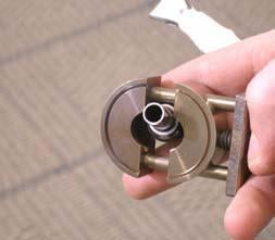
Interchanging of Hot Air Nozzles
1. Turn off the heat and power.
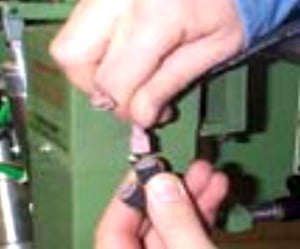
2. After the machine has cooled down properly loosen the nozzle clamp.
3. Hold the nozzle with a pair of pliers as the nozzle may still be to hot to touch.
4. Remove the hot air nozzle and nozzle clamp assembly.
5. Position the new hot air nozzle into the nozzle clamp assembly and position them onto the dual element housing.
6. Slightly tighten the nozzle clamp.
7. It is very important to align the hot air nozzle tip so that it is centered and squared on the weld roller and that the nozzle tip is square with the bottom track.
8. Turn power back on.
- Set the speed to zero. ONLY DO THIS IF THE MACHINE IS NOT RELEASING HOT AIR! Then press start to bring nozzle into welding position, the carriage will not move to allow for easy adjustment. Position the tip of the nozzle so it is aligned square with the weld roller and the bottom track. Lock down the nozzle clamp with a pair of pliers.
- With the nozzle square, turn up the speed to the desired setting. Turn the heat power back on and allow machine to heat up to desired temperature.
- See nozzle adjustment.
Weld Roller Cylinder Adjustment
- The pressure on the weld roller is created from the pneumatic cylinder used to pick up or put down the weld roller.
- The pressure on the weld roller is regulated and displayed on the control panel. The pressure needs to be set at least at 10lbs. If the pressure is not set the cylinder will not properly function.
- The speed of the weld roller up and down can be adjusted by the metering valves on the side of the air cylinder.
Nozzle Swing Cylinder Adjustment
- The hot air nozzle is automatically placed into or out of the position through the nozzle swing air cylinder.
- If the hot air nozzle is swinging to fast or to slow the speed of the swing action is controlled by the air flow metering valves located on the side of the air cylinder. Turning the screws in will slow the speed of the swing while backing the screws out will increase the speed.
- The hot air nozzle should be centered with the weld roller.
Cutter Adjustment
- If the machine is equipped with the butt seam laser. Align cutter to this laser line. If the machine does not have this option, Align cutter to inside overlap laser.
- First, jog cutter to starting position. The cutter should be adjusted square in the mounting clamp so when the cutter is put down, the foot sits on the track square. Then tighten the four bolts. However do not over tighten, this will pinch the air flow inside of the cutter, which will make the cutter not function.
- Second, the cutter clamp is attached to the machine. This controls the side to side adjustment and angle of the cutter foot. The cutter foot should be at a slight incline lifting the back of the foot slightly off the track. Too much of an incline will result in the cutter digging into the track. The cutter should be slid left or right to align the foot with the laser line. Tighten four bolts and run a test cut. Determine if the cutter is cutting on the laser line. If not move cutter left or right until cutter cuts on the line. Remember the angle of the foot may move every time cutter is slid left or right.
- Incase cutter is dropping to soon or to late. Log in to Maintenance page and adjust cutter length.
Micro-Switch Adjustments
This page will detail each of the Micro-switches and sensors on the Miller Weldmaster 112 Extreme.
- Overrun Limit Switch: The purpose of this switch is to stop the head carriage from over travel. *Note: This switch will initiate the Emergency Stop and take power and air from the machine.
- Return Home Slow Down Switch: The purpose of this switch is to slow down the head carriage when returning to the home position.
- Cutter Safety Switch: The purpose of this switch is to ensure that the cutter is in the up position in order to return to the home position.
Position Sensors
- Home Position Sensor: The purpose of this sensor is to tell the system the head carriage is in the home position, ready to run.
- Cutter Position Sensor: The purpose of this sensor is to tell the system the head carriage is in the position to cut.
- Forward Limit Sensor: The purpose of this sensor is to stop the forward motion of the head carriage.
Warning! Only a qualified technician may perform maintenance on this machine. This may be a Miller Weldmaster representative or someone trained by a Miller Weldmaster representative.
 Warning! This machine must be disconnected from its power source before any maintenance may begin.
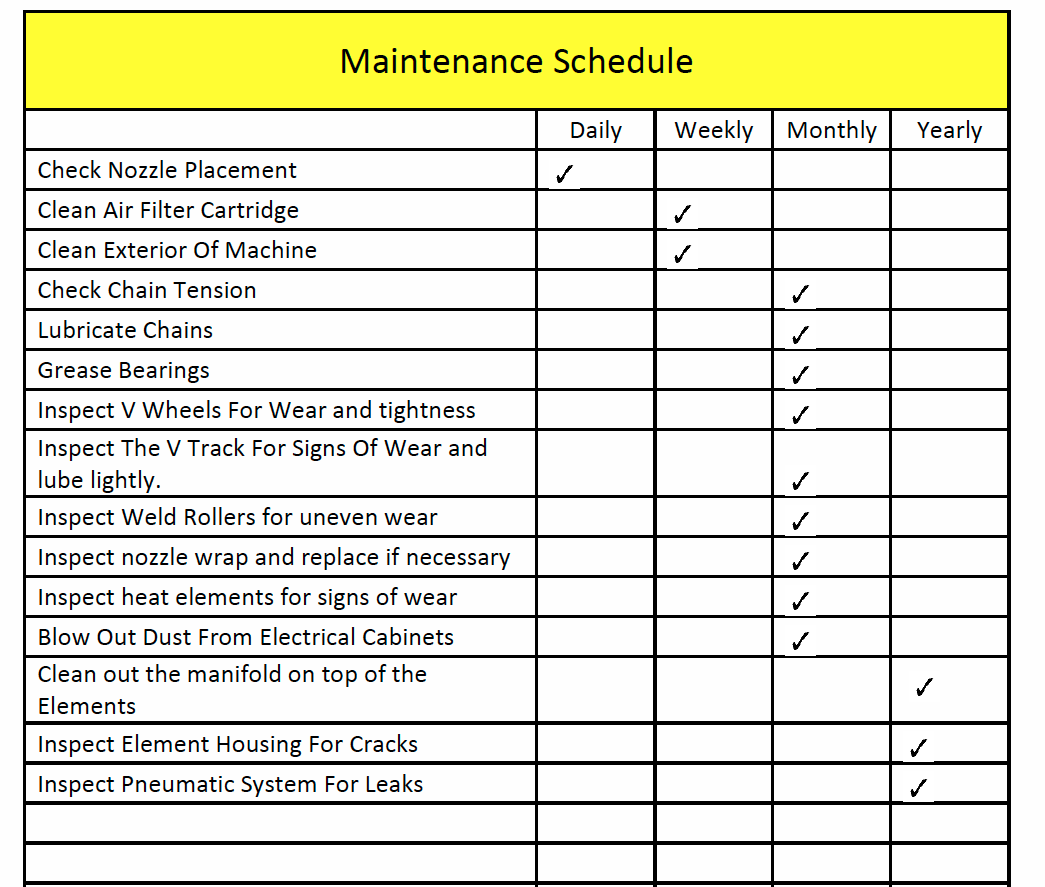
Maintenance
- Air Filter Cartridge: The Miller Weldmaster 112 Extreme has an Air Compressor that supplies airflow to the heat elements. Periodic cleaning and changing of the Air Filter Cartridge is necessary to maintain sufficient airflow. Insufficient airflow or any impurities in the airflow will shorten the life of the heat elements.
- Clean Air Filter Cartridge Every Week: If the surrounding conditions in your production area are not clean, it is recommended that you clean the Air Filter Cartridge twice a week.
Replacing Components
- Heat Elements: The heating elements used by the 112EX machine are rated for 1000 hours of use at 1000 degrees F (537 degrees C). Although longer heat element life is possible with proper maintenance, 1000 hours is the average. If the heat elements fail prematurely, contact a Miller Weldmaster representative before replacement.
- Chains: The 112EX machine has several chains that are used to drive weld rollers. Although not a high maintenance item, chains should be inspected once a month to ensure there is not excessive corrosion, rust, or dirt. Also inspect for any looseness or slack. If needed, lubricate chains once a month with 80w – 90w gear oil.
Adjusting the Upper Unit Weld Roller and Clutch Drive Chain
- Upper unit: When tightening the upper unit chain, you must check the weld roller for play. The weld roller should only move back and forth a 1/8 of an inch. Loosen the nut on the tensioning bolt. Once the nut is loosened turn the bolt clockwise until the weld roller doesn’t move. The back off the tensioning bolt counter clockwise until the weld roller achieves the 1/8 of an inch play.
- Long chain: The long chain adjustment is directly behind the upper unit where the upper unit attaches to the head post. Adjust the chain by adjusting the set screws for the bearing blocks that hold the upper unit on. By adjusting down on the set screws the chain will tighten. By adjust up on the set screw the chain will loosen.
- Main clutch chain: The Main chain to the clutch should be a little loose. Take the cover off the side of the head. Adjust the chain by loosening the idler sprocket brackets. There will be 2 idler sprockets. The chain should pull away from the idler sprocket approximately3/16 of an inch but not enough to come off the teeth. If the chain is too tight, the clutch will not work properly.
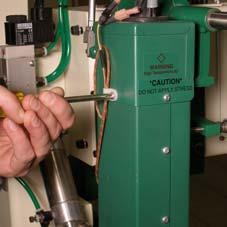
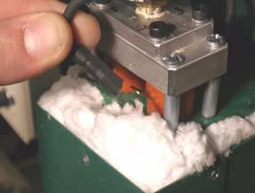
Changing the Thermocouple
The Moduline uses a thermocouple to read the air temperature just before it reaches the nozzle. The typical life expectancy of a thermocouple varies. The thermocouple should be replaced if the machine does not maintain a constant temperature of +/- 2 Degrees F (+/- 1 Degree C) or the heat elements burn out prematurely.
Warning! Only a qualified technician may perform maintenance on this machine. This may be a Miller Weldmaster representative or someone trained by a Miller Weldmaster representative.
Warning! This machine must be disconnected from its power source before any maintenance may begin.
1. Turn the Circuit Breaker to the off position.
2. Disconnect the power cord from the power supply. If the power cord is wired into the power supply, turn the power off at the junction box.
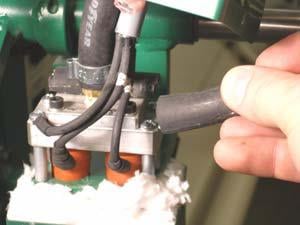
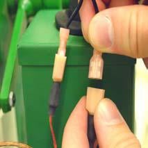
3. Unplug the 2 thermocouple leads.
4. Remove the hot air nozzle by loosening the clamp.
5. Remove thermocouple wire mounts.
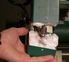
6. Remove the bottom cover and some of the fiberglass insulation from the element housing.
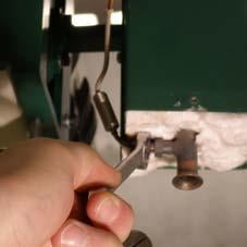
7. Using an 7/16 wrench, carefully loosen and remove the thermocouple nut.
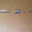
8. Install the new thermocouple with all the spacers in the sequence shown. Make sure the thermocouple is inserted all the way.
9. Tighten the thermocouple nut.
10. Reinsert the fiberglass insulation and bottom cover with screws bottom cover with screws.
11. Install both thermocouple wire mounts.
12. Install the nozzle and clamp. Make certain to install the clamp with the grooved side up.
13. Plug in the thermocouple leads. If the temperature starts reading backwards, flip the leads.
Changing the Heat Elements
The heating elements used by the Miller Weldmaster machine are rated for 1000 hours of use at 1000 degrees F (537 degrees C). Although longer heat element life is possible with proper maintenance, 1000 hours is the average. If the heat elements fail prematurely, contact a Miller Weldmaster representative before replacement. It is recommended that both elements be changed even if only one burns out.
1. Turn the Circuit Breaker to the off position.
2. Disconnect the power cord from the power supply. If the power cord is wired into the power supply, turn the power off at the junction box.
3. Unplug the 2 thermocouple leads.
4. Remove thermocouple wire mounts.
5. Remove the top covering of the element housing and slide it out of the way.
6. Remove the 2 pieces of insulation between the wire leads and the aluminum air divider.
7. Remove the 4 leads from the heat elements.
8. Loosen the 4 screws securing the aluminum air divider.
9. Remove the aluminum air divider.
10. Carefully remove the heat elements from the element housing.
NOTE: Inspect each element for any broken off fragments of glass or wire. Any missing fragments will be in the dual element housing or nozzle. These fragments must be removed before installing new elements.
11. Carefully install 2 new heat elements into the dual element housing.
12. Install the aluminum air divider.
13. Connect the four wire leads to the elements. Make sure wires #1 and #3 plug onto one element, and wires #2 and #4 plug onto the other element.
14. Inset the 2 pieces of insulation between the wires and the aluminum air divider.
15. Slide the top covering back onto the heat element housing. Make sure to feed the thermocouple connections through the top hole.
16. Install the 3 sheet metal screws to the top of the heat element housing.
17. Connect the thermocouple wire leads. If the temperature controller starts reading backwards, flip the leads.
8.0 Welding Tips
NOTE: The machine must have at least 90psi of air pressure in order to Reset power.
Loss of Welding Temperature
- Heat elements may be burned out, check number of hours on the heat elements. The heat elements are rated for 1000 hours at 73ºC.
- Thermocouple may be burned out or loose wires.
- Check wire connections to each heat element.
- Poor electrical connection on the supply line to the machine.
Air Cylinders Do Not Operate
- Check air pressure! Should be 90 PSI coming into machine.
- Meter valve on cylinder needs adjusted.
- Check solenoid valve for air pressure and voltage.
- If you have air pressure and voltage, the solenoid is bad.
Cutter
• Cutter not cutting on laser line.
- Cutter needs adjusted.
- Lasers need adjusted.
• Cutter not turning on.
- No air pressure to cutter.
• Cutter not dropping to track or dropping too fast.
- Metering valve on cutter slide needs adjusted.
• Cutter hitting clamp.
- Sensor for cutter Home Position needs adjusted. (See micro switches, sensor adjustments)
• Cutter leaking oil.
- Cutter oilier needs adjusted.
Hot Air Nozzle
• Nozzle hits clamp.
- Head carriage returned too far. (See micro switches, sensors)
• Nozzle hits track, weld roller or guide.
- Nozzle needs adjusted (see nozzle adjustment).
- Guide needs adjusted up.
• Nozzle moves when its activated to weld.
- Nozzle clamp loose (see nozzle adjustment).
Seam is Only Welded on One Side
• The hot air nozzle tip needs to be adjusted.
- Nozzle needs adjusted side to side.
- Nozzle may be pinched shut on one side. Open the pinched side so there is even flow.
- The speed control is set too high not allowing enough time for the hot air to be applied to the seam properly.
- There is a contaminant on the surface of the fabric being welded.
Overlap Seam
• Overlap seam is puckered on both sides of weld.
- Temperature is too hot. Turn down heat or speed up the machine.
• One panel is puckering and may be coming up short or long.
- The clutch pressure needs decreased if coming up short.
- The clutch pressure needs increased if coming up long.
• Overlap weld has a flap on one side of the weld.
- Guide needs adjusted side to side.
- Bottom panel not aligned properly.
• Overlap weld is less than weld size.
- Guide needs adjusted. Slide guide away from operator.
Pole Pocket
• Pocket seam is over puckering.
- Temperature is too hot. Turn heat down or speed up the machine.
• Pocket has wrinkles and twist.
- Material not started square.
- Clutch pressure needs adjusted. If top piece comes up short, decrease clutch pressure. If it comes out long, increase clutch pressure.
- Operator is pulling too much on material. Keep material straight during the weld with little pressure from operator against guide. Let the machine and guide do the majority of the work.
• Pocket has a flap on one side of the weld.
- Guide needs adjusted. Slide guide towards operator.
• Pocket weld is less than weld size..
- Guide needs adjusted. Slide guide away from operator.
Hem
• Hem is over puckering or burnt one side out.
- Temperature is too hot. Turn heat down or speed up the machine.
• Hem will not stay in guide.
- Guide not square, adjust guide.
- Add clutch pressure.
• Nozzle hits material.
- Nozzle too high. Lower nozzle.
- Material not tight between weld roller and guide due to not starting material square at the beginning.
• Hem weld has a flap on one side of the weld.
- Guide needs adjusted. Slide guide towards operator.
• Hem weld has a bead or pocket on one side of weld.
- Guide needs adjusted. Slide guide away from operator.
Hem and Rope
• Material too loose around rope.
- Adjust guide away from operator.
- Rope too small for guide.
• Material too tight around rope.
- Adjust guide toward the operator.
- Rope too big for guide.
• Hem and rope is over puckering or burnt one side out.
- Temperature is to hot. Turn heat down or speed up the machine.
• Hem and rope will not stay in guide.
- Guide not square adjust guide.
- Add clutch pressure.
• Nozzle hits material.
- Nozzle too high, lower nozzle.
- Material not tight between weld roller and guide due to not starting material square at the beginning.
• Weld roller runs over rope.
- Rope needs to be started on outside of weld roller.
Butt Seam
• Tape not centered in weld.
- Guide misaligned.
- Center of butt not aligned with laser.
- Laser line not centered with weld roller.
• Tape wrinkling.
- Too much clutch pressure.
- Too hot.
Truck Side Beading
• Indicator line does not line up with material.
- Guide misaligned.
• Nozzle hits beading.
- Nozzle too high.
• Wrinkles at the beginning.
- Material not clamped.
9.0 Additional Machine Documents