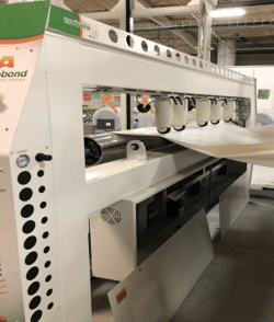
This instruction manual is intended to be a guide when operating the Moduline Gen II Multi Sealer welder. To ensure optimal performance from your welder, please follow the recommendations and specifications precisely.
Table of Contents
- Chapter 1: Intended Use
- Chapter 2: Electrical and Air Requirements
- Chapter 3: Explanation of Warnings
- Chapter 4: Principles of Heat Sealing
- Chapter 5: Start Up Procedure
- Chapter 6: Shutdown Procedure
- Chapter 7: Heat System Adjustments
- Chapter 8: Definition of Controls
- Chapter 9: Definition of Pneumatics
- Chapter 10: Definition of Components
- Chapter 11: Unwind Stand
- Chapter 12: Screen Shots
- Chapter 13: Maintenance
- Chapter 14: Troubleshooting
- Chapter 15: Spare Parts
- Chapter 16: Welding Tips
For more technical information regarding this machine call our Resolution Center at 1-855-888-WELD or email service@weldmaster.com.
1.0 Intended Use
The Miller Weldmaster Moduline Gen II Multi Sealer is intended to heat seal weldable thermal plastics such as:
- Non-woven polypropylene
- Vinyl (PVC) laminated fabrics
- Vinyl (PVC) coated fabrics
- Vinyl (PVC) films
- Polyurethane (PU) coated fabrics
- Polyurethane (PU) films
- Polypropylene (PP) coated fabrics
- Polyethylene (PE)
- Thermoplastic Rubber (TPR) film
- Thermoplastic Rubber (TPR) fabrics
- Rigid Extruded Products
The manufacturer does not approve of any other uses for this machine.
The manufacturer does not approve of the removal of any safety guards while the Moduline Gen II Multi Sealer is in operation.
The manufacturer does not approve of any unauthorized modification of Moduline Gen II Multi Sealer.
Only a properly trained technician may operate the Moduline Gen II Multi Sealer.
Only a properly trained technician may perform any routine maintenance to the Moduline Gen II Multi Sealer.
Only a properly trained technician may perform any repairs to the Moduline Gen II Multi Sealer.
Sealer only manufacturer approved replacement parts are to be used for the Moduline Gen II Multi Sealer.
The manufacturer will not be held liable for any damage or injuries occurring from any inappropriate use of this machine.
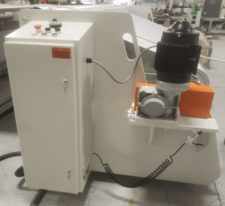
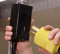
2.0 Electrical and Air Requirements
Warning! Only a qualified electrician may connect the electrical power.
Electrical supply:
The Moduline Gen II Multi Sealer has the following electrical requirements:
- 220 Volts
- 50/60 Hz
- 125 Amperes
- 3 Phase
Shop Air Supply:
The Moduline Gen II Multi Sealer includes an in-shop air supply valve that allows quick connects and disconnects to your shop air supply. Due to the number of different style airline connectors, a male quick connect is not included. You will want to select a male quick connect with a ¼ inch NPT (National Pipe Thread) to match your female quick connect.
The Moduline Gen II Multi Sealer requires the following shop air requirements:
- Minimum of 100psi at 10 cubic feet per minute.
3.0 Explanation of Warnings
There are several different warning symbols placed on the Miller Weldmaster Moduline
Gen II Multi Sealer. These symbols are to alert the operator of potentially hazardous areas on the machine. Familiarize yourself with their placement and meaning.
Caution Hot:
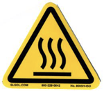
The “Caution: Hot” symbol is placed on a guard near hot surfaces.
Caution: Lockout:
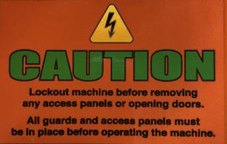
The “Caution: Lockout” sticker is placed near the opening of the cabinet and all access panels.
Warning: Moving Parts:
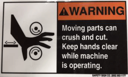
The “Warning: Moving Parts” sticker is placed on throughout the machine. Be aware of appendages around moving parts while machine is in motion
Warning: Keep Hands Clear:
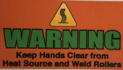
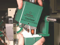
The “Warning: Keep Hands Clear” sticker is placed on the Heater Assembly. To prevent any pinching or burns, be aware of the location of your hands always.
Caution: Electricity:
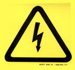
The “Caution: Electricity” sticker is placed near areas that contain electrical components. Power should be removed prior to opening any cabinet door.
Attention: Air Compressor:

The “Attention: Air Compressor” sticker is placed on the air compressors. These are in place to remind operators about preventative maintenance.
Danger: Pinch Points:
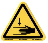
The “Danger: Pinch Points” symbol is placed near any potential pinch points. Do not place any body parts near these sections of the machine while the machine is running.
Safety Notes
Do not adjust the material while the machine is moving. Keep hands, long hair, loose clothing, and articles such as neckties away from the rollers have pinch points rollers to avoid entanglement and entrapment that can trap body parts or clothing and cause serious injury. Provide enough space around machine to ensure the safe and effective operation. The machine must be motionless and moving parts blocked before any cleaning, oiling, adjusting, repairs or maintaining work is done on any repairing or maintaining work is done on any part of the machine.
Always wear Personal protective equipment. (PPE) refers to protective clothing, helmets, goggles, or other garment designed to protect the wearer's body from injury.
4.0 Principals of Heat Sealing
Hot Air:
The heat required for the welding operation is created electrically by two heating elements located inside the heat element housing. The hot air temperature ranges from 100 to 1350 Degrees Fahrenheit or 25 to 730 Degrees Celsius.
Speed:
The speed of the weld rollers determines the amount of time the heat is applied to the material being welded. The slower the speed setting the more the material will be heated. To achieve the best weld, a minimal amount of heat should be applied to the material while still achieving a full weld. Too much heat will cause distortion of the material while not enough heat will prevent the material from welding.
Pressure:
The pressure of the weld roller is the final step when creating a weld. The pressure of the weld roller compresses the heated material together completing the welding process.
Summary:
When heat sealing, the correct combination of heat, speed and pressure will allow you to achieve a properly welded seam.
5.0 Start Up Procedure
Start Up Procedure
- Ensure that all cabinet doors are closed and locked.
- Ensure that all safety guards are in place.
- Rotate the in-shop air supply valve to the open position.
- Turn the main power disconnect to the on position.
- Press the blue reset button.
- Check for the proper alignment of the weld rollers. Make any adjustments necessary.
- Check for the proper alignment of the fabric guides. Make any adjustments necessary.
- Turn on the heat and adjust the temperature to the desired temperature.
- Check for proper adjustment of the heat system nozzles.
- Turn the swing button to the on position.
- Turn the motor button to the on position.
- Load all material that is needed for your welding operation onto the unwind stands.
- Properly place the material through the machine from the unwind stand(s).
- Once material is to the cell with the puller rollers, use the HMI to close the puller rollers.
- Turn on any remaining functions that will be needed for the welding process.
- Your machine is now prepared to weld!
6.0 Shut Down Procedure
Shut Down Procedure
- Clamp the material to the output end of the machine. This ensures the material will be in the proper position for the next production.
- Ensure the heat button is off. The temperature should start decreasing.
- The machine will not shut off immediately! The compressors will go through a 3-minute cool down cycle to allow the heat elements to cool off. These will then shut off.
- Ensure the tension from the unwinds are released by forward or reverse jogging the unwind. This will ensure the material does not pull out of the machine or guides when the circuit breaker is cut off and the pullers disengage.
- After the compressors have shut off, turn the main power disconnect to the off position.
- After the machine has shut off, rotate the in-shop air supply valve to the off position.
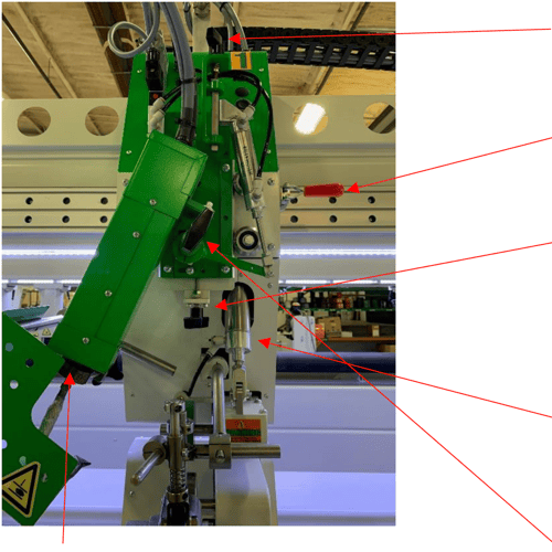
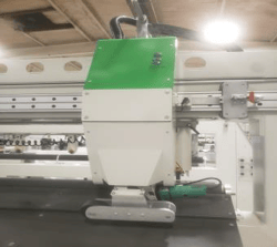
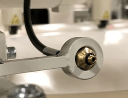
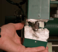
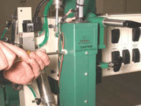
Side to Side Nozzle Adjustment: Moves the Nozzle left and right to the weld rollers.
Head Locking Clamp: Locks the head unit in the proper welding position.
Up and Down Nozzle Adjustment: Moves the nozzle up and down. Turning the nozzle adjustment knob clockwise, raises the nozzle Turning the knob counterclockwise lowers the nozzle.
Upper Unit Air Cylinder: Moves the upper unit up and down applying pressure to the lower weld rollers.
In and Out Nozzle Adjustment: Moves the nozzle in and out. Turning the adjustment knob clockwise moves the nozzle in and counterclockwise moves the nozzle out.
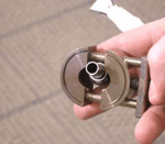
Nozzle Clamp: Locks the nozzle to the dual element housing in place.
Note: The groove side of the nozzle clamp must be facing up towards the dual element housing.

8.0 Definition of Controls
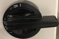
Main Power Disconnect: Will disconnect the machine from the power source if needed. This is also the lock out tag out point for the electrical source on the machine.

Emergency Stop: This is used in an emergency only. This will stop all functions of the machine and take it to a safe state. This will shut power off to any moving part of the machine and will turn the heat to the off position.

Reset Button: This button is used whenever the machine is turned on in the morning or an emergency stop button has been pressed. This is to signify the machine is clear and can start.

Start Button: Starts motion to the machine.
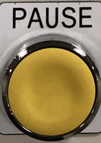
Pause Button: Pauses the machine from running.
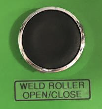
Weld Roller Open/Close: Will open and close the weld rollers for the specific head. There is also an open close button located on each individual head.
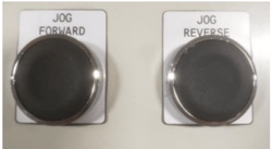
Jog Forward: This button will jog the unwind rollers forward, or in the direction of material travel.
Jog Reverse: This button will jog the unwind rollers in reverse, or in the opposite direction of material travel.
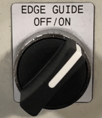
Edge Guide Off/On: This switch will activate the photo eye and linear actuator.
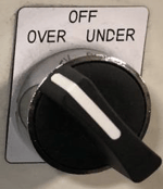
Over/Under: This switch will determine how the material pays off the unwinds. This will allow you to load the material any which way.
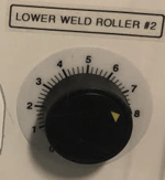
Upper/Lower Weld Roller Speed Control: This control will allow you to adjust the speed of the upper and lower weld rollers. This will ensure a good weld.
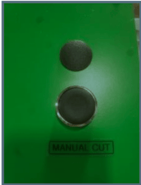
Manual Cut Button: When pressed the manual cut button will send the cutter in motion within the set range.
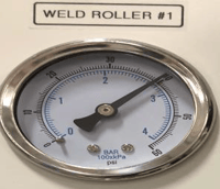
Weld Roller Pressure: The purpose of the weld roller pressure regulator is to vary the amount of pneumatic pressure between the weld rollers.
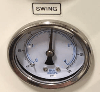
Nozzle Swing: Regulates the amount of air pressure used to swing the nozzle in and out.
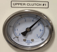
Upper Clutch Pressure: Applies torque to the upper weld roller. Or it increases the speed of the upper weld roller. This is used to help control the material.
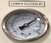
Lower Clutch Pressure: Applies torque to the lower weld roller. Or it increases the speed of the lower weld roller. This is used to help control the material.
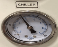
Chiller Pressure: The Chiller Pressure, regulates the amount of air pressure supplied to the Chiller.
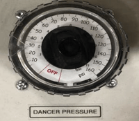
Dancer Pressure: This regulator controls the amount of tension on the up and down pressure of the dancer roller on the unwind stand. This is used to maintain web tension in the machine while in operation.
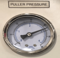
Puller Pressure: The purpose of the puller pressure regulator is to vary the amount of pneumatic pressure between the pullers.
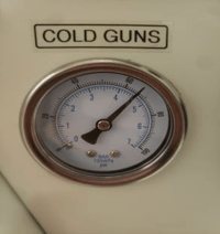
Cold Guns: The purpose of the cold gun pressure regulator is to vary the amount of pneumatic pressure from the cold guns when in use during welding.
10.0 Definition of Components
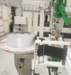
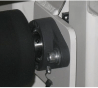
Unwind Stand: The unwind stands are designed to pay off the material at a controlled rate of speed to allow for material tension into the welding heads.
Automatic Material Cutter: The automatic material cutter assembly is designed to cut material off at any length the operator desires.
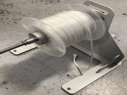
Rope Unwind Stand: This stand will allow the rope material to payoff correctly and smoothly going into the weld heads.
Keder payoff: The Keder payoff serves as a way to dispense Keder material smoothly into the guiding of the weld head.
Puller Frame: The output pullers are equipped with a driven nip roller. The upper nip roller will open and close.
Footage Counter: When in place allows the machine to count how much material has been run.
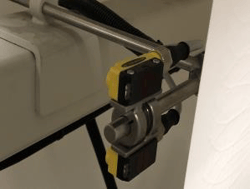
Photo Eye: This device is used on a linear actuated unwind stand to help keep the material constantly tracking in the same place.
Linear Actuator: Is used to move the unwind stand to maintain material placement. This works directly with the photo eye to maintain the tracking of the material.
Chiller: When activated will be used to keep material from overheating.
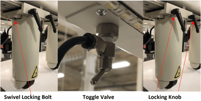
Puller Frame Components: Applies pressure to a roller that pulls the material through the machine. By loosening the Swivel locking bolt, the puller wheel can turn right and left for better control of the material. The locking knob will lock the puller system in place. Once in the proper place close the puller wheel with the toggle valve.
11.0 Unwind Stand
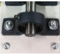
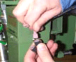
Safety Chuck: The safety chuck allows for quick change of material. Pressing on the top of the safety chuck we allow it to snap open so that the shaft may be removed or inserted. Once the shaft is inserted press against the top of the safety chuck to close it.
Removing the Shaft: To remove the shaft you must have the safety chuck top dead center to open. To open rotate the shaft to where the opening of the safety chuck is top dead center. Next you must open the turn handle. Once both safety chucks have been open use a crane or a forklift to remove the shaft.
12.0 Screen Shots
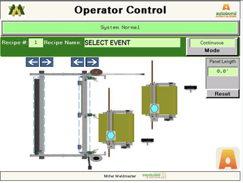
Operator Control Screen: This is the main screen the operator will use; this is the initial screen the machine will load.
Recipe #/Name: Displays the current recipe selected.
Panel Length: The top number will show the current panel’s length. The bottom number is the setpoint for the panel, this is adjusted in the Recipe Active screen.
Reset: This button will reset the encoder’s count for the current panel.
Mode: Will display to the operator the current mode the machine is running:
Continuous- The machine will run until pause or E-stop button is depressed.
Run To Set Point: The machine will run to a specific length set by the operator.
Batch: The machine will automatically run a specific number of batches.
To change any machine parameters, you must be logged in as the Operator;
User Name: oper
Password: 6789
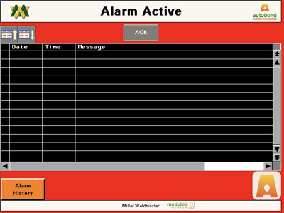
Alarm Active Screen: This displays the current active alarms, if any.
Ack: This button is used to acknowledge any active alarms.
Alarm History: This is used to pull up any and all old alarms ever present on the machine.

Recipe Active Screen: Displays all the current parameters for the selected recipe.
Recipe #/Name: This show the current recipe by number and by name.
Active Recipe Save: Pressing this button will save all the current parameters for the current recipe.
Drive Delay: Is the amount of time between the start of your welding head and the nozzles to swing in before the welding held will start.
Weld Unit # 1-3 This is the temperature set point we are setting each welding head at.
Cell #1 Master Speed: Controls the overall machine speed.
Cell #2 Panel Length: This will allow you to set the desired panel length for each recipe.
Cell #2 Sync Speed: This speed is slaved off of the master speed.
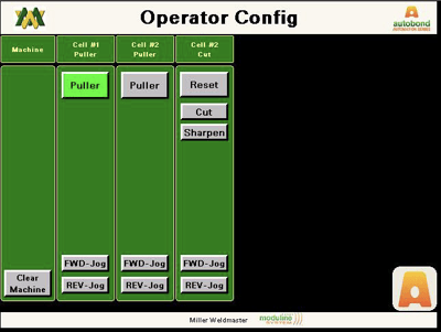
Operator Configuration Screen: Displays each cell with their appropriate functions.
Clear Machine: Will open the weld rollers, puller, and turns off the heat systems.
Cell #1 Puller: When illuminated, this will activate the puller on cell #1
Cell #2 Puller: When illuminated, this will activate the puller on Cell #2
FWD/REV Jog: These buttons will jog the cell forward or reverse.
Cell #2 Cut:
Reset: This will send the cutter to the home position if stopped during cycle.
Cut: This will set the cutter into motion.
Sharpen: This will allow the cutter to run while the operator depresses the sharpener.

Machine Stats: Displays the hour meter for the machine as well as all the individual welding heads. The hour meter is resettable when logged under the Tech level.
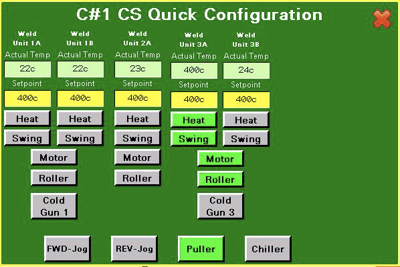
C#1 CS Quick Configuration Screen: This will display each welding heads current heat status.
Actual Temperature: This shows the actual current temperature of the machine welding head.
Setpoint: This shows the setpoint we want the machine to reach.
+/- Alarm Band: Used to setup the alarms for under/over set the set point temperature.
Heat: This button turns the heat on to the selected heat system on the selected cell.
Swing: This button turns on the heat system swing.
Motor: This button turns on the motor for the selected heat system on the selected cell.
Roller: This button will lower or raise the weld rollers
Cold Gun 1, 3: Turns on the auxiliary air chiller, this will be used for cooling the seam.
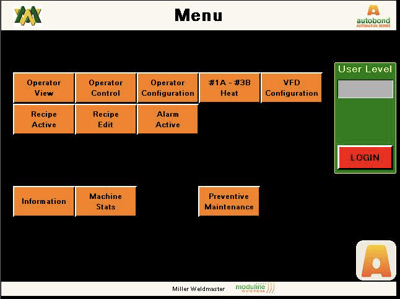
Menu Screen: The Main screen displays all available sub-menus for the machine control.
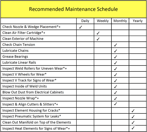
*Indicates replace parts as needed per inspection.
+Indicates parts that should be kept onsite.
13.0 Maintenance
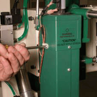
WARNING! Only a qualified technician may perform maintenance on this machine. This may be a Miller Weldmaster representative or someone trained by a Miller Weldmaster representative.
WARNING! Machine must be disconnected from power source before any maintenance can be done.
Bearings
The Miller Weldmaster Moduline Gen II Multi Sealer has several bearings, although not a high maintenance item, bearings should be inspected once a month to ensure there is not excessive corrosion, rust, or dirt. Also inspect for any looseness or wear. If needed, lubricate bearings once every 6 months with 80w–90w gear oil.
Air Filter Cartridge
The Miller Weldmaster Moduline Gen II Multi Sealer has an air compressor that supplies airflow to the heat elements. Periodic cleaning and changing of the air filter cartridge is necessary to maintain sufficient airflow. Insufficient airflow or any impurities in the airflow will shorten the life of the heat elements or the onboard compressor.
Clean the air filter weekly for best performance. Once you can no longer read the black text on the side of the filter cartridge it is time to replace the filter.
Common Components
Heat Elements
The heating elements used by the Miller Weldmaster Moduline Gen II Multi Sealer are rated for 1000 hours of use at 1000 degrees F (537 degrees C). Although longer heat element life is possible with proper maintenance, 1000 hours is the average. If the heat elements fail prematurely, contact a Miller Weldmaster representative before replacement.
Chains
The Miller Weldmaster Moduline Gen II Multi Sealer has several chains that are used to drive weld rollers and pullers. Although not a high maintenance item, chains should be inspected once a month to ensure there is not excessive corrosion, rust, or dirt. Also inspect for any looseness or slack. If needed, lubricate chains once a month with 80w – 90w gear oil.
Adjusting the Upper Unit Weld Roller Drive Chain
Upper Unit
When tightening the upper unit chain, you must check the weld roller for play. The weld roller should only move back and forth an 1/8 of an inch. Loosen the nut on the tensioning bolt. Once the nut is loosened turn the bolt clockwise until the weld roller does not move. Then back off the tensioning bolt counterclockwise until the weld roller achieves the 1/8 of an inch play.
Main Drive Chain
The main chain to the clutch should be a little loose. Take the cover off the top of the head. Adjust the chain by loosening the drive motor mount on the side of the head. There will be 2 idler sprockets. The chain should pull away from the idler sprocket approximately 3/16 of an inch but not enough to come off the teeth. If the chain is too tight, the clutch will not work properly.
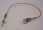
Changing Thermocouple
The Moduline Gen II Multi Sealer uses a thermocouple to read the air temperature just before it reaches the nozzle. The typical life expectancy of a thermocouple varies. The thermocouple should be replaced if the machine does not maintain a constant temperature of +/- 2 Degrees F (+/- 1 Degree C) or the heat elements burn out prematurely.
Warning! Only a qualified technician may perform any maintenance on machine. This may be a Miller Weldmaster representative or someone trained by a Miller Weldmaster representative
Warning! Machine must be disconnected from power source before any maintenance may begin.
1. Turn the main power disconnect to the off position.
2. Disconnect the power cord from the power supply. If the power cord is wired into the power supply, turn the power off at the junction box.

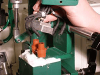
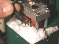
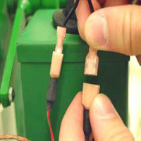
3. Unplug the 2 thermocouple leads.
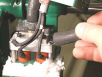
4. Remove the hot air nozzle by loosening the clamp.

7. Using an 7/16 wrench, carefully loosen and remove the thermocouple nut.
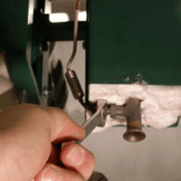
12. Install both thermocouple wire mounts.
Changing Heat Elements
The heating elements used by the Miller Weldmaster machine are rated for 1000 hours of use at 1000 degrees F (537 degrees C). Although longer heat element life is possible with proper maintenance, 1000 hours is the average. If the heat elements fail prematurely, contact a Miller Weldmaster representative before replacement. It is recommended that both elements be changed even if only one burns out.
1. Turn the main power disconnect to the off position.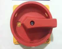
3. Unplug the 2 thermocouple leads.


8. Loosen the 4 screws securing the aluminum air divider.
9. Remove the aluminum air divider.

10. Carefully remove the heat elements from the element housing.
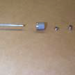
NOTE: Inspect each element for any broken off fragments of glass or wire. Any missing fragments will be in the dual element housing or nozzle. These fragments must be removed before installing new elements.
11. Carefully install 2 new heat elements into the dual element housing.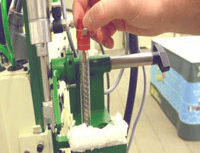

Troubleshooting your Moduline Gen II Multi Sealer
Frequently Asked Questions
Not a good Weld?
Check heat, speed, and weld roller pressure and nozzle placement. The tension on the unwind stands could affect the welding also.
I am burning a hole each time I start.
The drive delay time is set to high.
I have an unwelded part between the start and stop.
The drive delay time is set to low.
The material is not flowing through the guide smoothly.
Check alignment of each guide.
When I turn the main power disconnect on, the power does not seem to come on?
Check to see that the breaker is in the on position, make sure the shop airline is connected to the machine and the valve is turned to open. Check each e-stop button looking to see if any had been pressed. Upon finding an e-stop button that has been pressed check to make sure the machine is in a safe operable condition and all persons are standing clear. Twist the e-stop button clockwise to release it. Press the reset button on the main control panel.
I have the motor button is turned to the on position and when I hit start it does not move?
Have an electrician investigate the control box to see that all inverters read ready.
The temperature will not heat up.
Have an electrician check the fuse on the heater relay ensuring that it has not burned out. Check the heat elements, ensuring that they have not burned out. If all fuses and heat elements are good replace the heater relay.
The material is not moving through the machine.
Check to make sure the puller is closed.
The material will not stay in the guide
Check the brake pressure on the unwind stand. If pressure is correct than increase the upper clutch pressure.
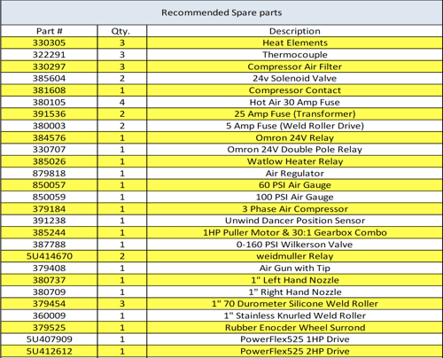
15.0 Spare Parts
16.0 Welding Tips
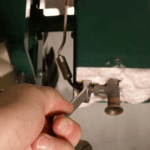
Welding Tips
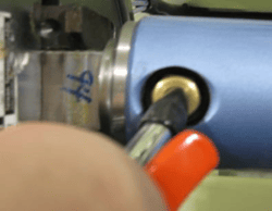
Bad Weld: This is not a good weld. Although the fabric is somewhat welded, it is not what would be considered 100%. One of two things must happen for this weld to become excepted. Either the speed must be decreased, or the heat must be increased.
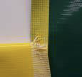
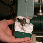
Good Weld: This is a good weld. The fabric is welded 100%. You can see that the fabric is delaminating over the entire width of the seam.

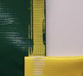
Upper Weld Roller Going Too Slow: This is an example of the upper weld roller going too slow. The green panel goes through the left side of the welder and the yellow panel goes through the right side. The upper weld roller is going slower than the bottom weld roller. This shows in the wrinkling of the bottom or left panel. The upper weld roller clutch pressure needs to be increased.

Upper Weld Roller Going Too Fast: This is an example of the upper weld roller going too fast. The green panel goes through the left side of the welder and the yellow panel goes through the right side. The upper weld roller is going faster than the bottom weld roller. This shows in the wrinkling of the upper or right panel. The upper weld roller clutch pressure needs to be decreased.

Too Much Shrinkage: This is an example of too much shrinkage in the material. Many thermoplastics tend to shrink when heated. This is caused by overheating.

Perfect Seam: This is an example of a perfect seam. There is no waviness, wrinkles, or puckers.
