This instruction manual is intended to be a guide when operating the Spec Extreme Seam welder. To ensure optimal performance from your welder, please follow the recommendations and specifications precisely.
Table of Contents
- Chapter 1: Introduction
- Chapter 2: Wedge Alignment & Adjustment
- Chapter 3: Wedge Cleaning
- Chapter 4: Wedge Removal and Replacement
- Chapter 5: Overlap Guide
- Chapter 6: Acrylic Overlap Guide
- Chapter 7: Hemming Guide
- Chapter 8: Hem Cord Guide
- Chapter 9: Pocket Guide
- Chapter 10: Flat Hem Guide
- Chapter 11: Acrylic Hem Guide
- Chapter 12: Keder Guide
- Chapter 13: Keder Framework
- Chapter 14: Material Set-Up
- Chapter 15: Operating Instructions
- Chapter 16: Motor Controls
- Chapter 17: Schematics
- Chapter 18: Wiring Diagram
For more technical information regarding this machine call our Resolution Center at 1-855-888-WELD or email service@weldmaster.com.
1.0 Introduction
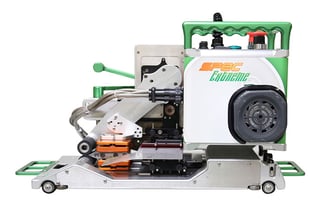
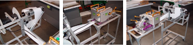
The Spec Extreme Welders are designed for the in-house fabrication of a wide range of flexible thermoplastics. This includes, but is not limited to, PVC, PP, PE, LDPE, urethane, geomembrane materials etc. Acrylic coated fabrics can also be welded with the addition of our Thermal Bonding Tape.
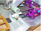
The Spec Extreme Welder uses a hot wedge as its heat source. Bonding of thermoplastics is achieved by a combination of Heat (temperature), Speed (exposure time), and Pressure (bonding force). The Spec Extreme Welder provides a smokeless and quiet operation during welding. The wedge also allows for the welding of thinner products without distortion.
We suggest that you make sample welds of your material to achieve the correct settings for Heat, Speed, and Pressure before you start welding your finished product. In addition, wedge alignment is critical to a quality weld. Be sure to review the wedge alignment section of this manual
1.1 Intended Use
The Triad Extreme Seam Welder is a hot wedge welding machine intended to heat-seal weldable thermal plastics such as:
- Vinyl (PVC) laminated and coated fabrics.
- Vinyl (PVC) and Polyurethane (PU) films.
- Polyurethane (PU) and Polypropylene (PP) coated fabric.
- Polyethylene (PE).
The manufacturer does not approve of:
- Any other uses for thesde machines.
- The removal of any safety guards while in operation.
- Unauthorized modification of the machines.
- Using replacement parts that are not manufacturer-approved.
 Only a properly-trained technician may operate and/or perform any routine maintenance or repairs to the machines.
NOTE: The manufacturer will not be held liable for any damage or injuries occurring from any inappropriate use of this machine.
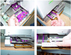
2.0 Wedge Alignment and Adjustment
Proper alignment of the wedge is essential to achieving a quality weld of the thermoplastic material. A variety of issues relating to the bonding of the material, flow of material through the machine, and the aesthetic finish of the weld can be attributed to the proper positioning of the wedge. It is therefore crucial to understand and practice the various adjustments for wedge alignment.It is recommended to review the alignment of the wedge:
- On a weekly basis
- When beginning new welding projects
- Changing wedge style and sizes
- Large variance of material weight or density
- Noticeable wedge wear
- Transportation of the machine
- Change in the operator of the machine
There are three alignments for the Spec Wedge: vertical, angle, and horizontal. The vertical alignment refers to the up and down position of the wedge in relation to the pressure rollers. The angle alignment refers to the wedge tip position with respect to being parallel with the pressure rollers. The horizontal alignment refers to the forward or aft position between the wedge tip and the pressure rollers.
Initially, the Spec Extreme Welder is aligned and tested at the factory. A visual review of the alignment should be made upon receiving the machine. In addition, sample welds should be made first to test the alignment as well as the material to be sealed before starting on an actual project.
 Begin all alignment adjustments with a cool, clean wedge.
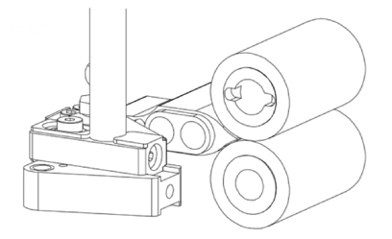
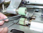
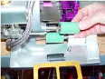
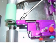
For the vertical alignment, the proper position should be the wedge tip centered between the pressure rollers.
|
Step 1: Take a small piece of the material to be welded, fold in half, and place it between the pressure rollers. Close the rollers together with the fold of material just inside the center of the roller |
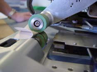 |
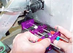
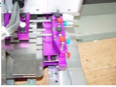
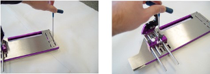
| Step 2: Engage the wedge lever into the welding position. Begin viewing the wedge tip position from the inner, pivot side. Slowly move the wedge in and out of the welding position; the wedge tip should just contact the fold of material | 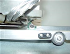 |
|
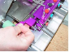
Step 3: If adjustments up or down is needed, use the 8mm hex wrench in the verticle adjustment. Turn the wrench clockwise or counterclockwise for either the up or down movement viewing from the pivot side. When adjustment is correct, view from the outer side of the wedge |
 |
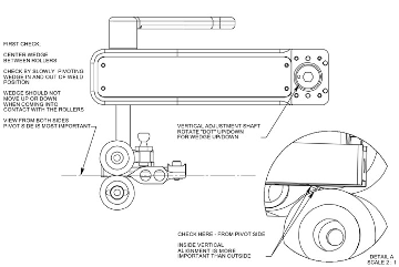
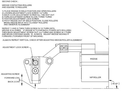
For the angle alignment, the proper position for most applications should be the tip of the wedge parallel to the pressure rollers.
|
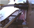
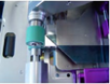
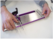
Step 1: Open the pressure rollers. Turn the wedge into the welding position. Make a comparison of the wedge to the bottom of the upper-pressure roller. To view this, adjust your field of vision at the rear of the Spec and above the welding are so that the tip of the wedge is seen just below the bottom edge of the upper-pressure roller |
 |
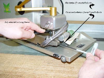
| Step 2: Adjust the angle of the wedge using a 4mm hex wrench in the angle adjustment screw located next to the wedge service pic in the wedge pivot housing. Viewing the position of the wedge tip, adjust if necessary. Turning the adjustment screw clockwise moves the outer edge of the wedge away from the pressure rollers. Turning the adjustment screw counterclockwise moves the outer edge of the wedge toward the pressure rollers. | 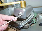 |
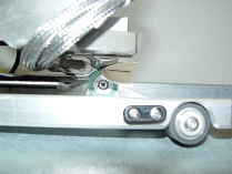
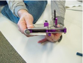
For the horizontal alignment, the wedge tip and surface should just make contact with the pressure rollers.
|
Step 1: Lower the pressure rollers together and engage the wedge into the welding position. View this alignment from the inside or pivot side of the wedge Step 2: To adjust, open the pressure rollers and place a 3mm hex wrench in the fwd/back adjustment screw located on the adjustment hub. Step 3: With a 4mm hex wrench, just loosen the adjustment locking screw |
 |
|
Step 4: Rotating the fwd/back adjustment screw clockwise will move the wedge tip away from the pressure rollers. Rotating the counterclockwise will move the wedge tip towards the pressure rollers. When changing directions on this screw that produce no movement of the wedge. Step 5: View the movement of the wedge above. Rotate the fwd/back adjustment screw in 1/4 to 1/2 turns at a time, checking in the new wedge position each time, checking the new wedge position each time. When completed, retighten the adjustment locking screw. Remove the two hex wrenches Step 6: Swing the wedge out of the welding position, close the pressure rollers, and engage the wedge in again to the welding position. Check the alignment as in step 1.
If further adjustment is necessary, repeat all steps. |
 |
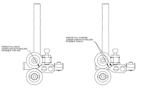
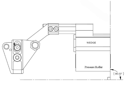
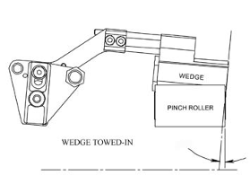
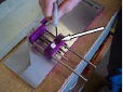
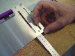
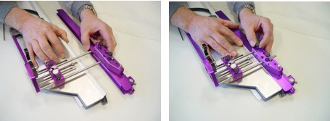
A special adjustment to the angle alignment should be considered for larger wedge sizes (30mm+), thicker materials, or to help control the material during the welding process. This application involves making a slight “toe-in” angle to the outer edge of the wedge.
|
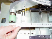
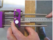
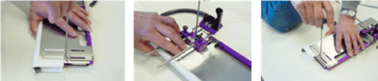
Step 1: Open the pressure rollers and remove the upper material guide tray Step 2: Place a straight edge against the outside edge of the wedge. Observe the angle between the straight edge and pressure rollers. This should initially be 90 degrees. |
 |
|
Step 3: Place a 4mm hex wrench in the angle adjustment screw located next to the wedge service pin on the wedge picot housing Step 4: Turn the wrench counterclockwise so that the outside tip of the wedge makes an inward movement toward the pressure rollers. Use the straight edge against the edge of the wedge to again determine the "towed-in" angle. The exact angle needed is at your discretion; initially make a 5-degree change and then make test welds to determine the results. |
 |
3.0 Wedge Cleaning
The welding of various thermoplastics will result in burned coating residue which will accumulate on the surface of the hot wedge. Cleaning of the wedge is required daily if not several times depending on the accumulation and resulting quality of the weld. The wedge should be cleaned after heavy use, changing thermoplastic materials, or if not in use for long periods of time.
The best way to clean the surface of the wedge involves burning the residue to the point it is released from the metal surface and is easy to blow or brush off.
| Step 1: With the wedge in the stowed position, turn the wedge engagement lever in slightly and loosen the wedge service bolt (or service pin) to allow the wedge engagement lever to rotate out farther than the stowed position to the service position |  . .  |
| Step 2: Increase the temperature of the wedge to 510 degrees. Allow sufficient time for the residue to be backed off the wedge, typically 5 to 10 minutes. | 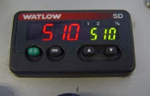 |
| Step 3: Once the residue is loosened from the metal, blow or gently brush it to eliminate it. Do not scrub the metal surface as it will be scratched and worn. If reside is still present, allow more time to continue this process. When cleaned, lower the temperature and rotate the wedge back into the stowed position. | 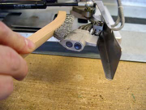 |
When changing to different size seam widths, the hot wedge will need to be removed and replaced with a different wedge. In addition, if the wedge no longer heats, wedge alignment is no longer effective, or the wedge surface is worn or destroyed, the wedge must be replaced. Always work with a cool wedge with the power switched off and electrically disconnected from the power source.
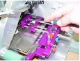
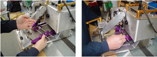
| Step 1: With a cold wedge, rotate the wedge out to the service position as described in Wedge Cleaning Chapter 3. Remove the two clamps holding the electrical wires secure to the machine using a Phillips head screwdriver | 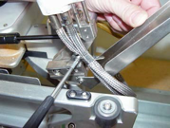 |
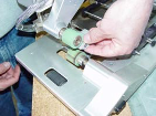
| Step 2: Tilt the Spec Extreme welder on its side. Once the clamp is located under the arm of the wedge mount arm. The other is on the inside corner of the wedge pivot. | 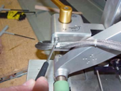 |
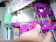
| Step 3: Electrically disconnect the wedge wires from the Spec control box by unscrewing the locking ring and gently pulling the connector from the socket | 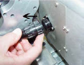 |
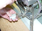
| Step 4: Loosen the two locking screws from the clamping system of the wedge retaining the rods to the wedge mount arm. Pull the wedge from the clamp and remove | 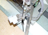 |
To install a new wedge:
|
Step 1: Position and insert the two retaining rods from the wedge into the clamping system on the wedge mount arm. Slightly tighten the two set screws to hold the wedge to the arm Step 2: rotate the wedge engagement lever so the wedge is in the welding position. |
|
|
Step 3: Adjust the position of the wedge side relative to the lower-pressure roller. Most often the wedge tip will match the size of the roller. In other cases, the wedge tip may be smaller and should be centered in the lower-pressure roller. Step 4: Carefully rotate the wedge back out to the service position and secure the two cap screws for the clamp. Re-check the position of the wedge to the roller. Step 5: Electrically connect the wedge wires to the Spec control box by twisting. the braids near the connector so that it lines up with the socket, insert and rotate the locking ring clockwise to secure Step 6: Replace the two electrical wire clamps to their respective position as in #2 of the removal process Step 7: With the installation of a new wedge it is recommended to perform a wedge alignment especially if the wedge removed was well worn. |
 |
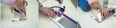
5.0 Overlap Guide
Material guides are used to properly position the material in the welding area. These upper and lower guide trays can be adjusted in three different directions to provide versatility in a variety of applications. The guide trays can be moved up and down, towards or away from the pressure rollers, and side to side. Depending on the particular application and material that is being welded, testing for different configurations may be helpful.
| Step 1: Loosen the two thumb screws on each of the adjustment frames. Use a Phillips head screwdriver to turn the adjustment frame. By rotating in one direction or the other, the guide tray will move up or down. | 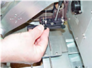 |
| Step 2: With the wedge in the welding position, view from the side to adjust the upper material guide tray to the intended height. | 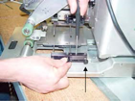 |
| Step 3: For the lower guide tray, close the pressure rollers on the cold wedge in their welding position and turn the adjustment screw to adjust to the intended height. When completed, retighten the thumb screw. | 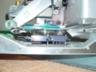 |
| Step 1: For the upper material guide tray, use a 4mm hex wrench to loosen the cap screw which holds this adjustment frame to the guide mount. | 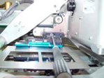 |
| Step 2: With the large slot in the adjustment frame, the guide tray can be placed forwards or backward. Positioned away from the pressure rollers to allow for more preheat of the material as it approaches the welding area. Position towards the rollers where preheat would be minimized. When placed in the desired position, tighten the cap screw. | 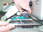 |
| Step 3: For the lower material guide tray, turn the Spec Extreme welder on its side to locate and loosen the two Phillips head screws which secure the guide mount to the base. The guide mount can be placed within the slot in the base of the Spex towards or away from the pressure rollers with similar results to that of the upper material guide tray. When placed in the desired position, tighten the two Phillips head screws. | 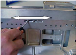 |
To adjust the upper and lower material guide trays side to side.
|
Step 1: With the wedge in the welding position, place a straight edge against the guiding edge of each guide tray, extend out towards the pressure rollers, and view from above the rollers to properly position them. Step 2: For the upper guide tray, loosen the two thumb screws located on the top clamp plate used to secure the guide tray to the retaining rods and slide to adjust. With the straight edge against the guide tray edge, match the edge of the pressure roller and/or the inside edge of the wedge. |
 |
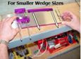
| Step 3: Removal of the upper guide may be necessary so the upper guide tray positioning set screw can be adjusted. Turn clockwise for a larger wedge size and counterclockwise for a smaller wedge size. Adjust the screw so the guide tray stops in the correct position. | 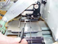 |
| Step 4: When positioned correctly, retighten the thumb screws on the clamping plate to secure. For the lower guide tray, use a 2mm hex wrench to loosen the two set screws located on the top of the adjustment frame. Slide the lower guide tray to adjust to the proper position | 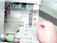 |
| Step 5: With the straight edge against the lower guide tray edge, match to the edge of the pressure roller and/or to the outside edge of the wedge. When positioned, tighten the two set screws to secure. | 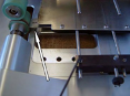 |
Front Guides are provided for positioning the material as it enters into the Spec Extreme Welder. These front guides can be adjusted according to the specific style and size wedge being used.
|
Step 1: Use a 2mm hex wrench and loosen the appropriate set screw(s) for the upper or lower material front guide. |
|
Step 2: Position a straight edge against the edge of the previously adjusted upper and lower material guide trays and extend the straight edge beyond the front of the Spec. |
| Step 3: Slide the appropriate material front guide until it makes contact with the straight edge. Repeat steps 2 & 3 for the other material front guide. |
|
Step 4: When positioned correctly, tighten the set screws to secure. |
For overlap welding, enter the two sheets of material from one side and the other and insert each edge up against the guides. The lower sheet is placed in between the two plates for the lower material guide tray and against the guide edge. The upper sheet is placed on top of the upper material guide tray and against the guide edge. Extend the overlapped material to the pressure rollers, position them correctly, and lower the rollers to secure them. Engage the wedge in to weld.
6.0 Acrylic Overlap Guide
For welding with the Thermal Bonding Tape on acrylic-coated fabrics, a guiding system has been developed to position the tape correctly.
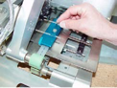
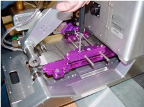
| Step 1: Install the tape dispenser to the front rail on the top of the Spec. Position the dispenser to the end of the rail above the tape front guide. | 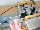 |
|
Step 2: Place a roll of Thermal Bonding Tape within the dispenser and feed the tape through the tape front guide and the lower section of the Spec body |
 |
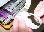
| Step 3: Remove the upper material guide tray so that the tape can be fed through the tape guide located on the lower material guide. Pull the tape out and lap over the lower-pressure roller. Reinstall the upper material guide tray. | 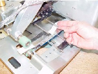 |
To overlap weld acrylic coated materials using the Thermal Bonding Tape, enter the material from both sides of the Spec and place the edge of the material against the guides. Make sure the tape is in the correct position and not confined or twisted. Position the overlapped material and tape at the pressure rollers and lower the rollers to secure them. Engage the wedge to begin welding.
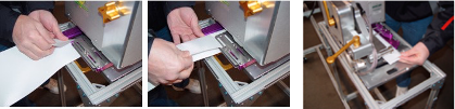
7.0 Hemming Guide
When the Spec Hem Welder is assembled at the factory, the top edge guide has been positioned correctly with the particular wedge size that is installed. If the wedge size is changed, the top edge guide will need to be adjusted when the new wedge is installed.
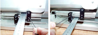
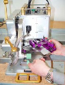
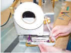
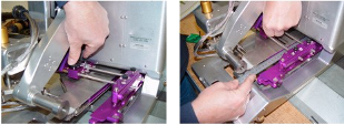
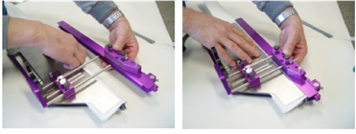
| Step 1: Begin by removing the entire hem guide system from the Spec machine. With the wedge in the service position, remove the cap screw from the guide mount with a 4mm hex wrench. Carefully pull out and remove the entire guide system and set it aside to work with. | 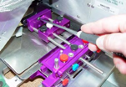 |
 |
| Step 2: Loosen the two black thumb screws on the top of the outer guide and slide the two guide sections completely apart. | 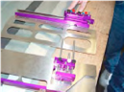 |
|
| Step 3: Working on the inner hem guide portion, loosen the two clamping cap screws for the top edge guide using a 3mm hex wrench. One of these screws is in the front of the inner hem guide; the other is recessed in the adjustment block between the black and white thumb screws. | 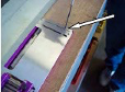 |
 |
| Step 4: The inner top guide edge is a narrow metal strip sandwiched between the top two plates of the inner hem guide assembly. It will slide towards or away from the edge of the inner hem guide by applying force on the front clamping cap screw and the adjustment block against either edge of the inner hem guide. | 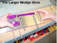 |
 |
|
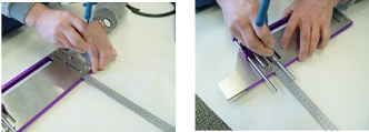
Step 5: Place a ruler within the two upper plates of the inner hem guide assembly to measure the distance from the inner top edge guide to the edge of the plates. Match this measurement with the new wedge size to be installed. Check this measurement in two places to make sure the inner top edge guide is straight. |
|
|
| Step 6: When completed, tighten the two clamping cap screws. Re-assemble the inner and outer sections of the hem guide, carefully re-insert the hem guide into the Spec machine, and tighten the cap screw through the guide mount to secure the hem guide to the Spec machine. | 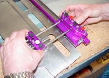 |
 |
| Step 7: Turn the wedge into the welding position. Loosen the two black thumbscrews on the top of the adjustment block. Place a straight edge against the top edge guide and extend out towards the pressure rollers. Adjust the inner section of the hem guide so the straight edge (top edge guide) matches the inside edge of the wedge. The outside edge of the wedge should match the edge of the upper section of the hem guide. When positioned, retighten the black thumbscrews. | 
|
 |
| Step 8: Loosen the black thumb screws on the top of the outer guide and slide the outer guide into the inner guide until it stops. Re-tighten the black thumb screws. | 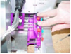 |
 |
|
Step 9: Loosen the white thumb screw on the adjustment block and slide the outer guide set rod out until it touches the outer guide adjustment block. Re-tighten the white thumb screw. |
 |
8.0 Hem Cord Guide
| Step 1: Loosen the two red thumb screws on top of the outer guide adjustment block as well as the third red thumb screw located in the front of the hem guide underneath the lower section of the outer guide assembly. | 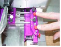  |
| Step 2: Looking from the side of the Spec Welder at the outer guide adjustment block, locate the Phillips head screw for adjusting the outer fold guide. It is located under the center mounting block of the outer guide | 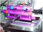 |
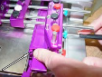
| Step 3: Use the Phillips head screwdriver to adjust the outer fold guide edge. The adjustment desired should be according to the rope or cord size. Turn clockwise for larger rope or cord size. Turn counterclockwise for a smaller rope or cord size. Use a sample of the rope or cord within the inner and outer fold guides to measure. Also, allow room for the fold of material. When the inner fold guide edge is positioned correctly, tighten the three red thumb screws. | 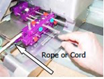 |
9.0 Pocket Guide
|
Step 1: Loosen the two black and red thumb screws on top of the outer guide adjustment block as well as the third red thumb screw located in the front of the hem guide underneath the lower section of the outer guide assembly (refer to Pg. 19, Step 1). Step 2: Slide the outer guide completely out and re-tighten the two black thumb screws. |
|
| Step 3: Adjust the outer fold guide edge of the outer guide by sliding it into the outer guide adjustment block to create a maximum-size opening in the guide tray. When positioned, re-tighten the three red thumb screws. |  |
|
Step 4: Locate two set screws accessible through two holes located near the inside edge of the inner hem guide section. One hole is at the front of the hem guide. The other hole is just in front of the inner hem guide adjustment block. Use a 2mm hex wrench to slightly loosen these screws. Step 5: At either end of the inside edge of the upper hem guide section, reach in and slide the inner fold guide out towards the outer guide. The distance extended will define the size pocket to be made. When the inner fold guide edge is positioned, re-tighten the two set screws. |
  |
To weld a pocket, loosen the two black thumb screws on the top of the outer guide adjustment block and slide the outer guide completely out. Folding the material over to create the pocket shape, enter the edge of material into the hem guide and against the top guide edge. Slide the material the length of the guide and out beyond the pressure rollers. Adjust and position the material at the welding area, slide the outer guide in to confine the material, and retighten the black thumb screws. Re-position the material again and lower the pressure rollers to secure. Engage the wedge in to begin welding. When welding, be attentive to the flow of material entering into the hem guide and the edge of the material against the top guide edge.
10.0 Flat Hem Guide
To set up for the flat hem style weld, the addition of a lever pressure arm to the hem guide as well as a change to larger pressure rollers will be made.
|
Step 1: Loosen the two black and red thumb screws on top of the outer guide adjustment block as well as the third red thumb screw located in the front of the hem guide underneath the lower section of the outer guide assembly(refer to Pg. 19, Step 1). |
 |
|
Step 2: Slide the outer guide out slightly and re-tighten the black thumb screws. |
 |
| Step 3: Locate the two dowels on the inside edge of the outer guide center adjustment block. Attach the lever pressure arm to these dowels making sure there is a step down from the outer guide to the lever pressure arm. Use the screw provided to secure | 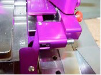 |
|
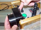
Step 4: Change the pressure rollers by removing the screw and washer from the axle shaft, sliding off the existing roller, and install the larger roller with the same screw and washer. Make sure the locking pin on the axle shaft seats in the roller. |
 |
|
Step 5: Note: To allow room between the lever pressure arm and the pressure rollers, use a 4mm hex wrench to loosen the hem guide adjustment mount cap screw. Slide the hem guide fully forward in the adjustment slot and re-tighten the cap screw. |
 |
|
Step 6: Loosen the two black thumb screws on the top of the outer guide adjustment block, slide the outer guide back in towards the inner guide section until it stops, and re-tighten the thumb screws |
 |
|
Step 7: Locate the outer fold guide adjustment screw (see page 20, figure 2). Using a Phillips head screwdriver, turn counter clockwise to adjust the inner fold guide edge completely out until the movement stops. This should place the outer fold guide edge against the inner fold guide edge. When positioned, tighten the three red thumb screws. |
 |
|
Step 8: Note: As a test, when the wedge is turned in to the welding position, pressure should be exerted by the side of the wedge against the lever pressure arm to compress the arm in slightly. This pressure is important for the melting of the thermoplastic around the fold for the flat hem finish. |
 |
To weld, the flat hem, loosen the two black thumb screws on the top of the outer guide adjustment block and slide the outer guide out slightly. Folding the material over, enter the edge of the material into the hem guide and against the top guide edge. Slide the material the length of the guide and out beyond the pressure rollers. Adjust and position the material at the welding area, slide the outer guide in to confine the material and re-tighten the black thumb screws. Reposition the material again and lower the pressure rollers to secure. Engage the wedge to begin welding. When welding, be attentive to the flow of material entering into the hem guide and the edge of the material against the top guide edge.
11.0 Acrylic Hem Guide
For welding with the Thermal Bonding Tape on acrylic-coated materials, a guiding system has been developed to position the tape correctly.
|
Step 1: Install the tape dispenser to the front rail on the top of the Spec motor box. Position the dispenser to the end of the rail above the tape front guide Step 2: Place a roll of Thermal Bonding Tape within the dispenser and adjust the dispenser if necessary for the tape to clear the pressure adjustment knob. |
 |
|
Step 3: Feed the tape through the short portion of the tape guide then turning the tape at a right angle and feeding through the length of the tape guide path contained in the hem guide assembly. |
  |
|
Step 4: When the tape appears at the end of the guide, extend the tape out and over the lower-pressure roller. |
 |
To weld acrylic-coated materials using the Thermal Bonding Tape, proceed at this point with the previous instructions for performing the three hem weld styles
12.0 Keder Guide
When the Spec Keder Machine is assembled at the factory, the top and bottom edge guides have been positioned correctly for the width of the material and PVC cord that is being ordered with the machine. If changing to different width material, PVC cord, and/or different style keder (single or double fold), the top and bottom edge guides will need to be adjusted. To adjust:
|
Step 1: Begin by removing the entire keder guide system from the Spec machine. With the wedge in the service position, remove the two Phillips head screws from the guide mount and side of the machine. Carefully pull out and remove the entire guide system and set aside to work with. |
 |
|
Step 2: Loosen the two black thumb screws on the top of the outer cord channel guide and slide the two guide sections completely apart. |
 |
|
Step 3: Working on the inner Keder guide section, loosen the two clamping cap screws for the top edge guide using a 3mm hex wrench. One of these screws is near the front of the guide; the other is just in front of the adjustment block. |
 |
|
Step 4: Follow the same procedure as step 3 to loosen the two clamping cap screws directly behind the ones completed in step 3. This will loosen the bottom edge guide. One of these screws is recessed in the adjustment block between the black and white thumb screws. |
 |
|
Step 5: The inner top guide edge is a narrow metal strip sandwiched between the top two plates of the inner keder guide assembly. It will slide towards or away from the edge of the inner keder guide by applying force on the front clamping cap screws and pushing or pulling in either direction against either edge of the inner keder guide. |
 |
|
Step 6: For a double flap keder, insert a sample of the proper width of material as well as the proper diameter PVC cord to be completed. Adjust the inner top guide edge to touch the top edge of material. Slide the bottom edge guide up against the top edge guide and check for the lower edge of material touching the bottom guide edge. |
 |
|
Step 7: When completed, hold both the material and cord in position while tightening the two sets of clamping cap screws. |
 |
|
Step 8: For a single flap keder, slide the top material guide edge fully forward. If needed, use a ruler to measure the distance between the top material guide edge and the edge of the inner keder guide section. This should be near 10mm in distance. When completed, tighten the two clamping cap screws. |
|
|
Step 9: As with the double flap described in step 6, insert a sample of the proper width of material as well as the proper diameter PVC cord to be completed. Place the top edge of material against the top material guide edge just completed in step 8. Slide the bottom edge guide up against the lower edge of material. When completed, tighten the lower material guide edge clamping cap screws.
|
 |
|
Step 10: Re-assemble the inner and outer sections of the keder guide system tightening the black thumb screws to secure. |
Double Flap Keder
Single Flap Keder
|
|
Step 11: Carefully re-insert the hem guide into the Spec machine, properly line up the dowel pins, and re-insert & tighten the Phillips head screws through the guide mount to secure the keder guide system to the Spec machine.
|
 |
|
Step 12: Turn the wedge in to the welding position. Loosen the two black thumbscrews on the top of the adjustment block. Place a straight edge against the side of the wedge and slide the inner keder guide section out to match the straight edge. When positioned, retighten the black thumbscrews.
|
 |
|
Step 13: Check to make sure the wedge moves cleanly from the welding position to the stow position and back. If it scraps within the inner keder guide section, loosen the two set screws on the side of the adjustment block and use a Phillips head screwdriver on the screw within the adjustment block to raise or lower the guide section |
 |
|
Step 14: Check the alignment of the outer keder guide section. If it needs centering to the inner section, loosen the two set screws on the side of the guide mounting block and use a Phillips head screwdriver on the screw within the mounting block to raise or lower the outer guide.
|
 |

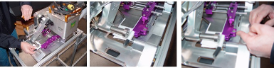
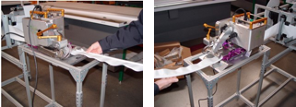
13.0 Keder Framework
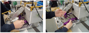
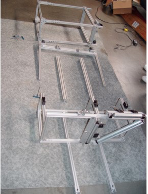
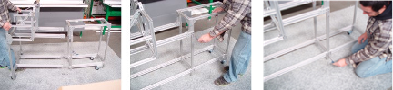
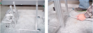
A special framework has been designed to hold the Spec Keder Machine and deliver the PVC material and cord. This framework comes partially disassembled and will need to be completed. Depending on the shipping configuration, the framework may be pictured in one of the various breakdowns below. Locate the appropriate breakdown of your shipment below and complete the necessary assembly.
|
Step 1: Removing the framework from the packing box(es), layout the various sections on the floor to separate. It is possible to have 2, 3, or 4 different sections. |
 |
|
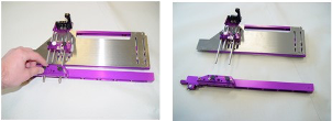
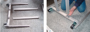
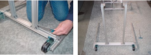
Step 2: The first assembly may be the lower base support pieces to the front leg and roller support. Place the support pieces into the angle connection and tighten the screws. The completed should look like the picture below. |
|
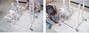
|
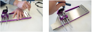
Step 3: Lay the completed front leg support section on its side and position the material delivery section of the framework in a similar manner. The legs should fit up and into the brackets attached to the material delivery section. Tighten screws on both legs. |
|
|
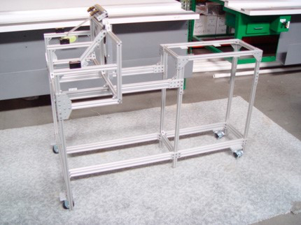
Step 4: Place the completed front section of the framework upright with the roller wheels on the ground. Upright the machine support section of the framework on its roller wheels. The two sections can now be joined. Tighten all screws associated with these two sections. |
 |
|
Step 5: As a completed assembly, the Keder Delivery System framework should look like the picture below.
|
 |
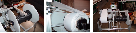
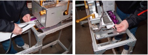
13.1 Keder Material & Cord Set Up
|
Step 1: Slide the spool of PVC cord through the longer of the two roller shafts located at the end of the framework for the delivery system. Position the spool correctly on the shaft and use the end clamps to secure. The cord should now be thread through the hole and extended out towards the Spec Keder machine. Follow the same procedure for installing the roll of material |
 |
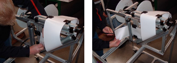
|
Step 2: Feed the material though the upper retaining blocks and over the horizontal roller. Adjust the retaining blocks if necessary to secure and direct the material. Turn the material around the diagonal roller and feed through the lower retaining blocks. Again adjust the lower retaining blocks if necessary. Finally feed the material around the vertical roller and extend out towards the Spec Keder Machine. |
 |
|
Step 3: Fold the material and begin to feed the lower fold into the lower guide opening of the keder guide system. Fold over the upper portion of the material and enter this into the upper guide opening of the keder guide system. Carefully slide the material through the guide system until it is out beyond the welding area. |
 |
|
Step 4: Feed the cord within the fold of material and slide through the keder guide system. Bring the end of the cord out from the material at the welding area. |
 |
|
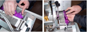
Step 5: Push the threaded lever on the side of the outer guide section inward to release the pressure lever arm. Carefully slide the outer guide in towards the inner guide section and position the material and cord correctly within the guide system. Tighten the two black thumbscrews on the outer guide when complete. |
 |
|
Step 6: Position the material and cord again within the keder guide system and pinch the material tight around the cord. Lower the lever for the pressure rollers so that a tight fit is accomplished between the material wrapped around the cord. Pull the threaded lever counterclockwise to move the pressure lever arm out and lock it against the fold of material and cord. |
 |
|
Step 7: The following are pictures from various angles of the material set-up. |
 |
|
Step 8: When the material, cord, keder guide system, and proper temperature, speed, and pressure of the Spec Welder are properly positioned, swing the wedge lever arm in to make several test strips of welded keder. Adjust any or all segments of the material setup to make changes for a smooth running output of keder. |
 |
14.0 Material Set-Up
Material should be laid out as flat as possible, either on the floor or table depending on how you set up your fabrication area. With most material and especially thinner goods, it is preferred to pull out the wrinkles or pull taunt. The use of sheet metal in or next to the machine on the table, allows for the use of magnets to position and hold the material. Taping material taunt is a good practice.
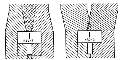
To perform overlap welds, always overlap material more than the final weld width. Example: With a 1 1/2” weld width, overlap the end of the material or run 2 to 2 1/2”. The machine will push the material to the desired overlap. If the material is not overlapped or positioned properly, the machine will not make the desired overlap weld. See example below.
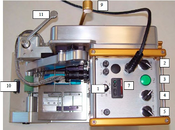
15.0 Operations Instructions
- Turn the Power Switch #2 on. The Green Power Light #3 will go on with a one second delay. The Green light will remain on as an indicator that you have power to the heaters.
- Temperature Controller #7 will come on with a 1-2 second delay after Green Power Light goes on. Units are set in Celsius at the factory. Press the up or down button until you reach your desired temperature. Heat up time is only one to two minutes. Do not adjust heat over 510 degrees C. For sample welds, set controller to 400 degrees C. This may not be your final setting.
- Set For/Rev Switch #4 to Forward position. This indicates direction of machine and drive /pressure roller movement.
- Set Man/Auto Switch #5 to Auto position. This will engage or start Drive/Pressure rollers when wedge is moved into welding position.
- Swing Drive Wheel Assembly #10 under bottom Pressure Roller. This will make the machine move automatically. With Drive Wheel Assembly out, the machine can be used in a stationary mode.
- #1 is the Speed Control. It is adjustable from 0-30 feet per minute. Normal settingwill be in the 30 to 60% range, for 12-30 mil goods.
- Insert material into the machine with proper guides installed and close Pressure Wheel Handle #9.
- Swing Wedge Engagement Handle #11 in toward the machine, this will automatically start forward motion of the Spec and engage wedge with material.
- Adjust speed control up or down until you can verify you are getting a proper weld.
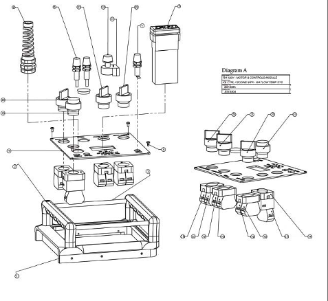
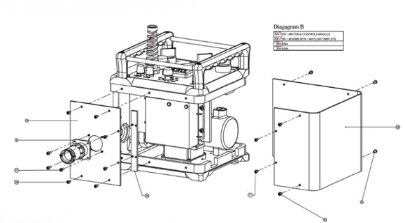
16.0 Motor Controls
16.1 RH-120v-Motor & Controls Module-Diagram A&B
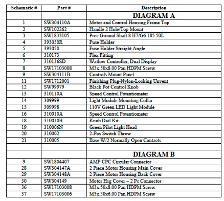
16.2 RH-120v-Motor & Controls Module-Diagram C

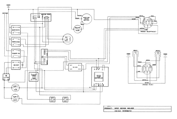
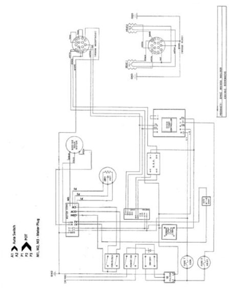
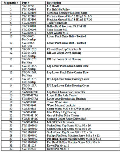
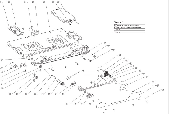
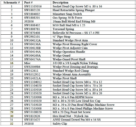
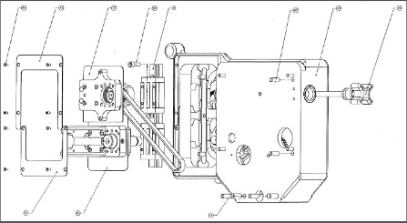
17.0 Schematics
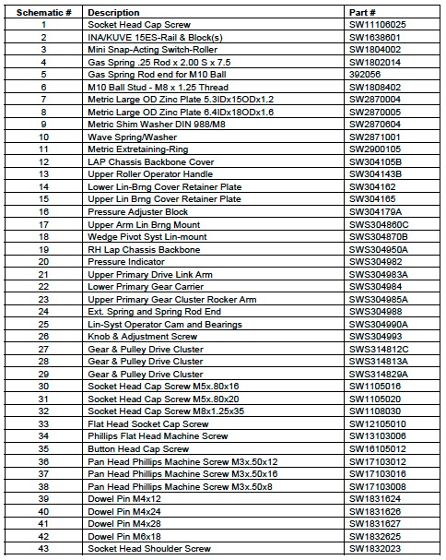
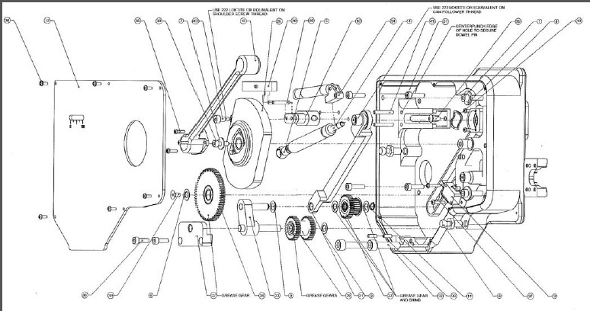
17.1 RH Lap Weld Rolling Chassis Base-Diagram D
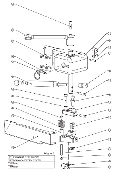
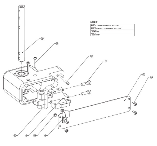
17.2 Wedge Pivot Housing-Diagram E&F
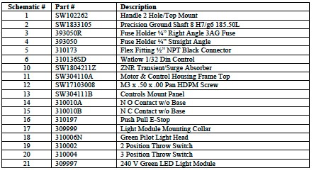
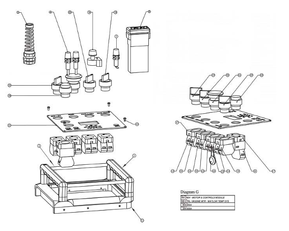
17.3 RH-240V Motor & Controls Moduline-Diagram G
17.4 Chassis Backbone & Control
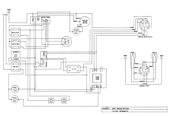
18.0 Wiring Diagram
18.1 110V
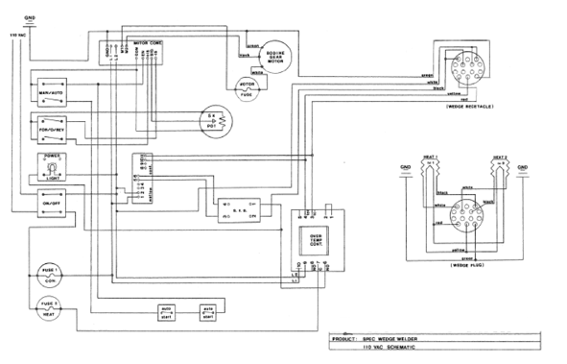
18.2 220V