This instruction manual is intended to be a guide when operating the Triad Extreme Seam welder. To ensure optimal performance from your welder, please follow the recommendations and specifications precisely.
Table of Contents
- Chapter 1: Introduction
- Chapter 2: Material Set-up
- Chapter 3: Operating Instructions
- Chapter 4: Material Guides
- Chapter 5: Welding
- Chapter 6: General Maintenance
- Chapter 7: Wedge Cleaning and Honing
- Chapter 8: Wedge Adjustment
- Chapter 9: Wedge Replacement
- Chapter 10: Wedge Installation
- Chapter 11: Troubleshooting
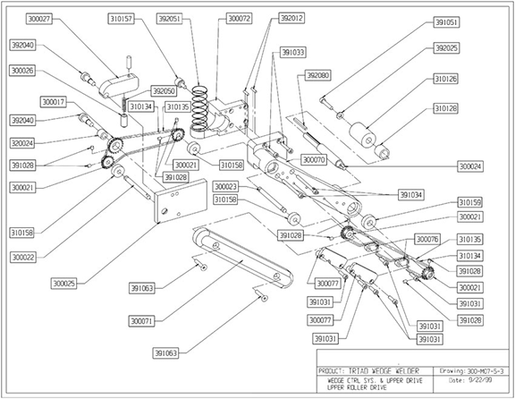
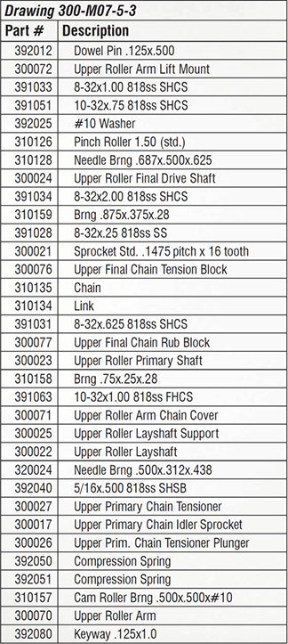
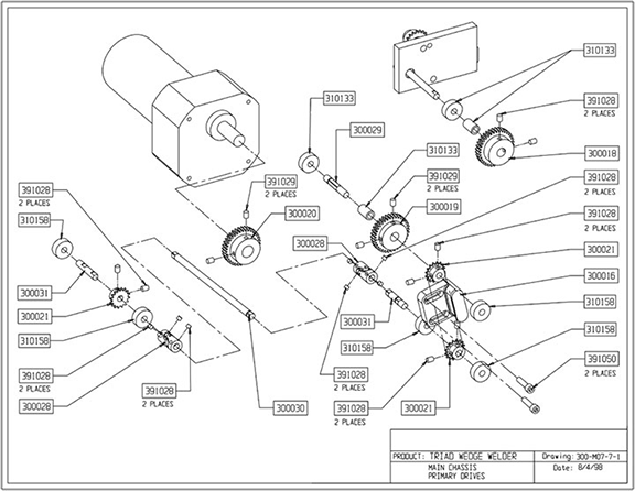
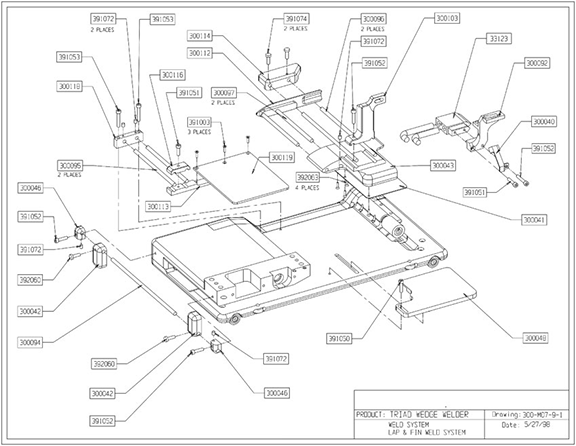
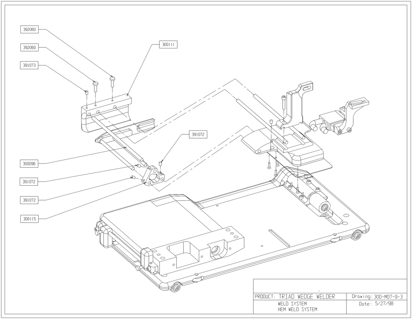
- Chapter 12: Schematics
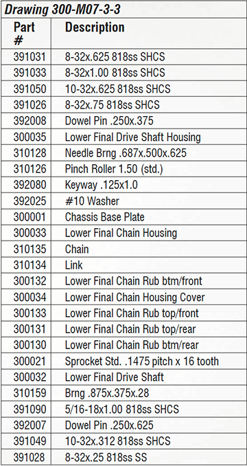
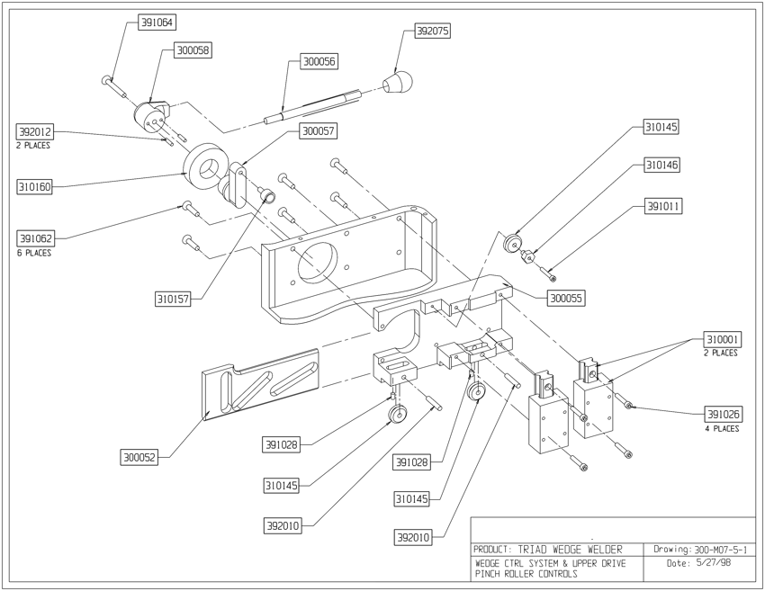
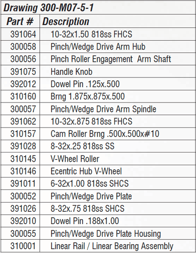
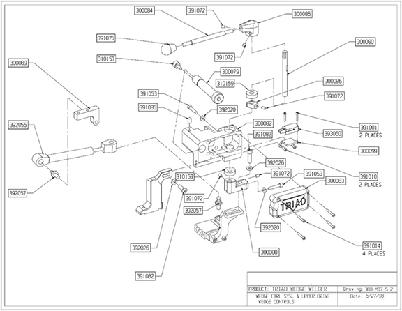
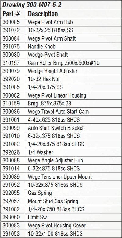
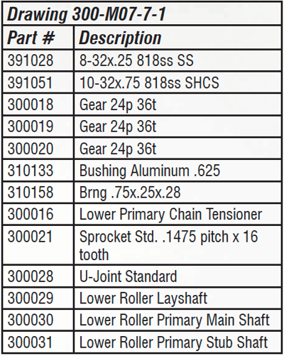
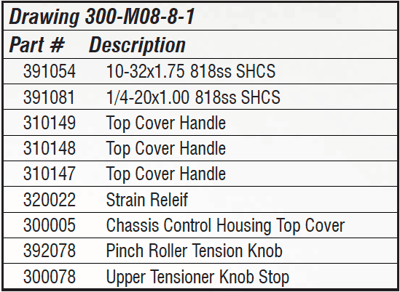
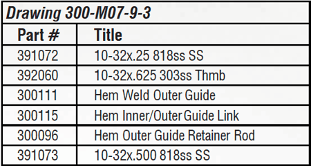
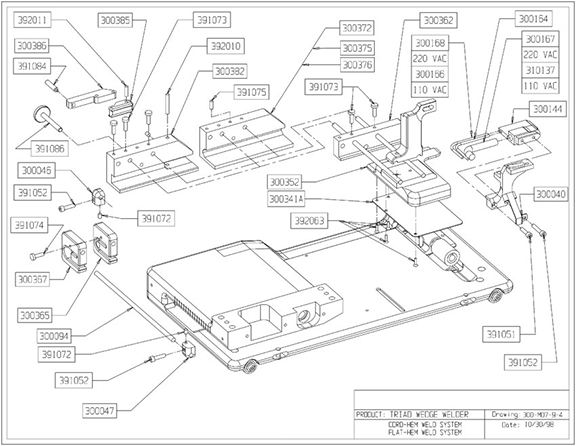
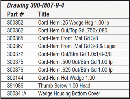
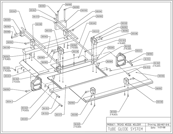
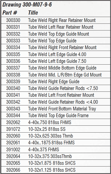
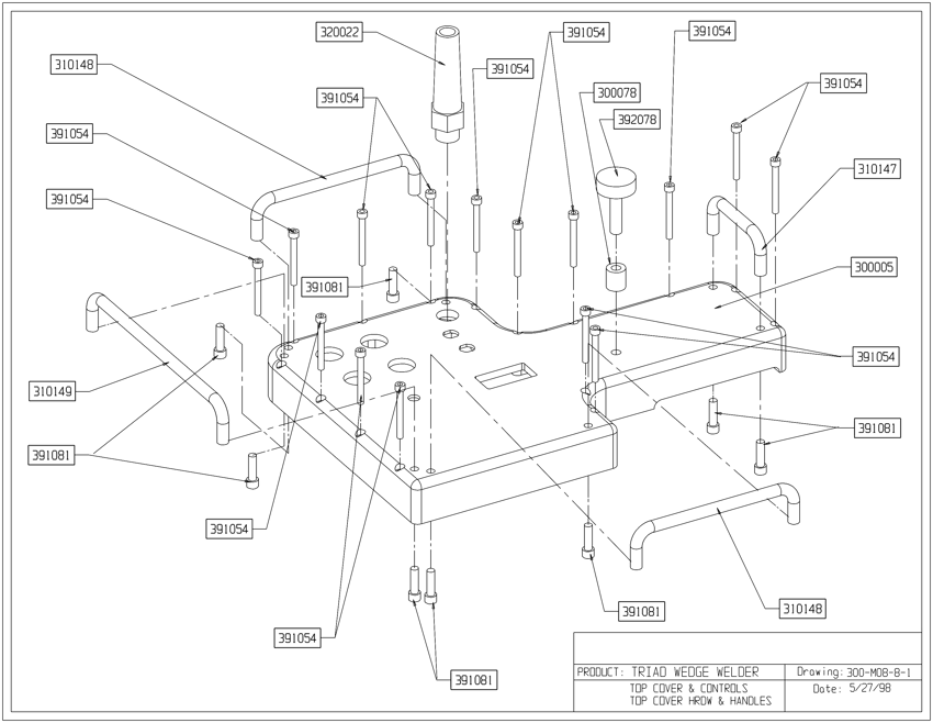
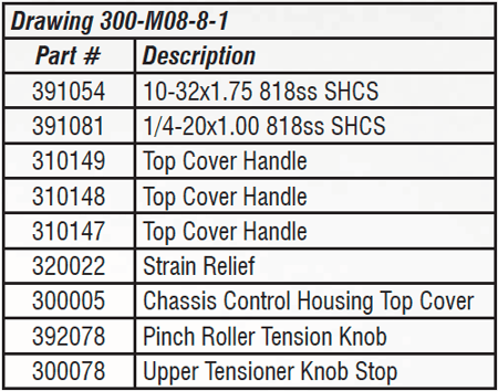
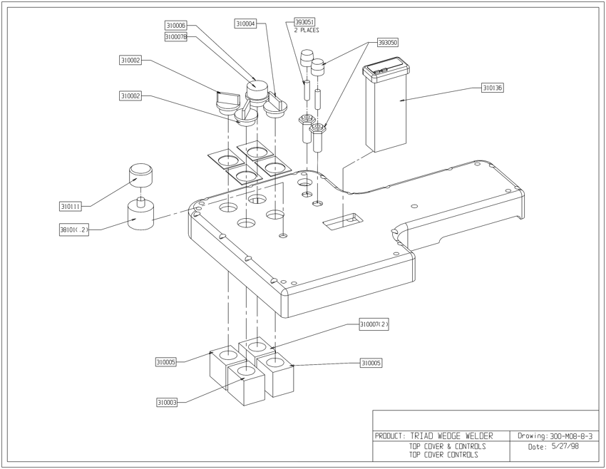
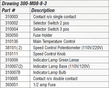
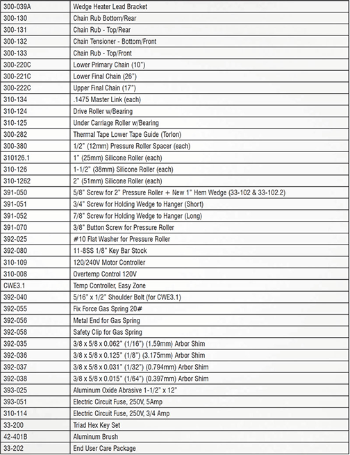
- Chapter 13: Commonly Used Parts
- Chapter 14: Additional Machine Documents
For more technical information regarding this machine call our Resolution Center at 1-855-888-WELD or email service@weldmaster.com.
1.0 Introduction
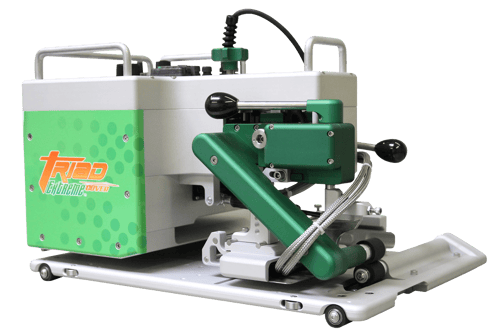
The Triad Extreme Seam hot wedge welding machine is designed for in house fabrication of a wide range of flexible membranes. This includes, but is not limited to, PVC, PP, PE, LDPE, Urethane, etc.
Thickness of material that can be welded will vary also with product. Normal range is 5-100 mil thickness and can be supported or non-supported material.
The Triad comes complete with three different guides. This will allow you to perform the overlap weld, hem weld, prayer weld and many more welding options.
The Triad uses a hot wedge as its heat source. This method will give you smokeless and quiet operation. The wedge also allows for welding thinner products without distortion.
The Triad can be used as a stationary welder or in an automatic mode. When using the Triad in an automatic mode, a track system is suggested. Please refer to Track System Specifications.
We suggest that you make samples welds of your product to achieve the correct settings for heat, speed and wedge alignment before you start welding
1.1 Intended Use
The Triad Extreme Seam Welder is a hot wedge welding machine intended to heat-seal weldable thermal plastics such as:
- Vinyl (PVC) laminated and coated fabrics.
- Vinyl (PVC) and Polyurethane (PU) films.
- Polyurethane (PU) and Polypropylene (PP) coated fabric.
- Polyethylene (PE).
- Thermoplastic rubber (TPR) film and fabrics Non-woven Polyester and Polypropylene Various Weldable Webbing.
The manufacturer does not approve of:
- Any other uses for these machines.
- The removal of any safety guards while in operation.
- Unauthorized modification of the machines.
- Using replacement parts that are not manufacturer-approved.
 Only a properly-trained technician may operate and/or perform any routine maintenance orrepairs to the machines.
NOTE: The manufacturer will not be held liable for any damage or injuries occurring from any inappropriate use of this machine.
2.0 Material Setup
Material should be laid out as flat as possible, either on the floor or table depending on how you set up your fabrication area. With most material and especially thinner goods, it is prefered to pull out the wrinkles or pull taunt. The use of sheet metal in or next to the machine on the table, allows for the use of magnets to position and hold the material. Taping material taunt is a good practice.
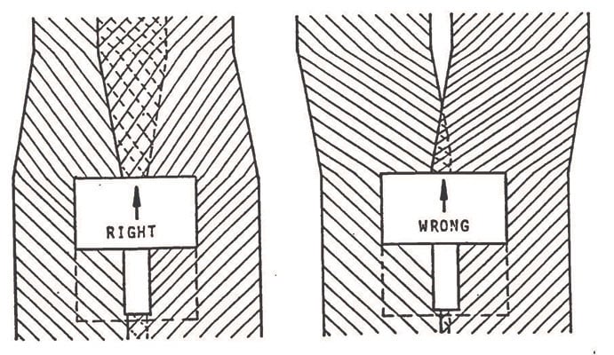
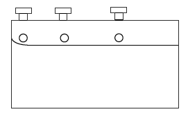
To perform overlap welds, always overlap material more than the final weld width. Example: With a 1-1/2” weld width, overlap the end of material or run 2 to 2 1/2”. The machine and front guides will push the material to the desired overlap. If the material is not overlapped or positioned properly, the machine will not make the desired overlap weld. See sample below.
3.0 Operating Instructions
The following procedures should be followed only after you have followed the Wedge Adjustment and Guide adjustment procedures.
-
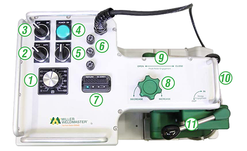
Pull up on Red Power Switch #3 to turn machine on. The Green Power Light #4 will go on with a one second delay. The Green light will remain on as an indicator that you have power to the machine. (Push down on Red Power Switch #3 to turn machine off)
-
Temperature Controller #7 will come on with a 1-2 second delay after Green Power Light goes on. Units are set in celsius at the factory. Press the Set Button and hold, now press the up or down button until you reach your desired temperature. Heat up time is only one to two minutes. Do not adjust heat over 510 degrees C. For sample welds, set controller to 400 degrees C. This may not be your final setting.
-
Set For/Rev Switch #5 to Forward position. This indicates direction of machine and drive/pressure roller movement.
-
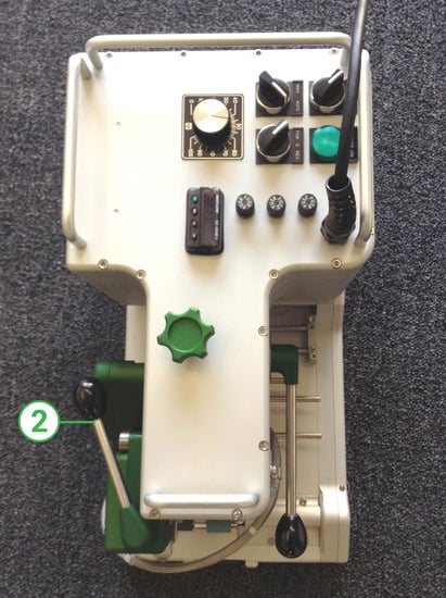
Set Man/Auto Switch #2 to Auto position. This will engage or start Drive/Pressure rollers when wedge is moved into welding position.
-
Swing Drive Wheel Assembly #10 under bottom Pressure Roller. This will make the machine move or automatic. With Drive Wheel Assembly out, the machine can be used in a stationary mode.
-
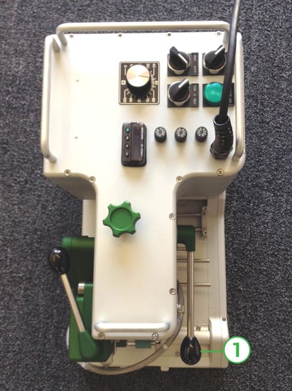
#1 is the Speed Control. It is adjustable from 0-30 feet per minute. Normal setting will be in the 30 to 60 range, for 12-30 mil goods.
-
#8 is the Pressure Knob. It can be adjusted for more or less pressure, depending on the thickness of material.
-
Insert material into the machine with proper guides installed and close Pressure Wheel Handle #9.
-
Swing Wedge Engagement Handle #11 in toward the machine, this will automatically start forward motion of the Triad and engage wedge with material.
-
Adjust speed control up or down until you can verify you are getting a proper weld.
4.0 Material Guides
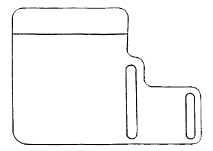
All Guides shown below are included with the purchase of the standard machine. Each guide will give you a specific type of weld and more. You can only use one guide system at a time.
The Top Guide will be used with all three different welding functions, overlap, hem and prayer welds. All Guides are adjustable.
To achieve a precise weld with no loose flap on top or bottom of sheet, guides should be adjusted so that they are even with the width of wedge, or welding area.
Overlap Guide
Top Guide
Hem Guide
Prayer or Fin Guide
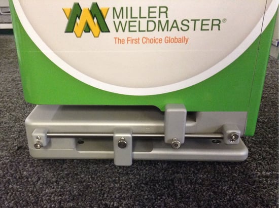
5.2 Hem Weld
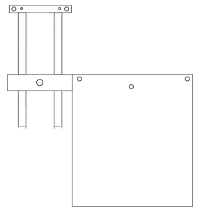
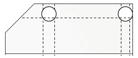
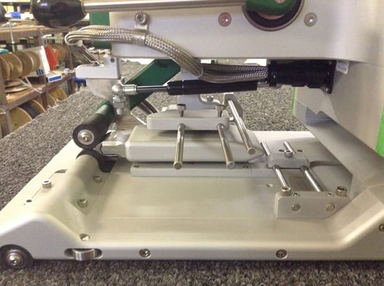
Slide Hem Guide #2 onto the three stainless rods up to the outer Horn Guide #3 (Diagram #1), leaving enough area between the two so material will slide easily. Tighten thumbscrew (B) (Diagram #1), this will allow the outer Horn guide and Hem guide to move as one. This dictates the size of the hem to be welded. Push on Hem Slide #4 (Diagram #2) to achieve desired hem width or size. When this is done, tighten thumbscrews (C) (Diagram #1) to lock in place.
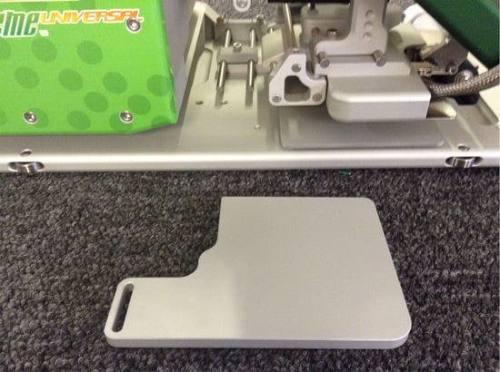
5.3 Prayer or Fin Weld
Position the Prayer Guide #5 under the Welding Horn, placing the key way into the slot. Fasten with screw provided once proper alignment is completed.
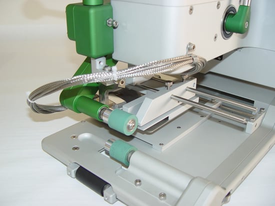
5.4 Front Guides
Front Guides #6 are adjustable to pre-align material before you reach the welding process. This will help the operator in feeding material into machine properly.
6.0 General Maintenance
General maintenance should be performed annually to your Triad Extreme Welder.
Chain tension should be checked to alleviate excessive wear to the chains and sprockets. Using a foaming chain lubricant will cling to the chain and extend chain life.
The pinch rollers should be replaced if there are cuts, flat spots, burn marks etc.
Wedge adjustment should be checked daily before performing any welding. The operator should be familiar with all wedge adjustments to get the best weld quality. Check for any loose hardware. Loose hardware can alter the wedge adjustment with every engagement.
For accurate welds and longer wedge life, the wedge should be cleaned and honed on a regular basis.
CLEANING: Wedge cleaning should be done daily. There are two ways to clean the wedge.
-
With the Pressure Rollers in the up position and the wedge in the weld position, use the Brass Brush provided and clean wedge top and bottom. This can be done after every weld or as needed.
-
The second method of cleaning the wedge is to increase the temperature to 510 degrees C for 5-10 minutes. This will burn the residue on the wedge and it will flake off. Use the Brass Brush to remove.
HONING: Wedge Honing should be done if there are signs of wear on the wedge. This is evident with uneven welds, rounding edges or corners on the wedge.
-
Install both smooth steel rollers on machine, (do not hone the wedge with the Silicone rollers on machine).
-
Turn the forward/reverse switch to reverse position.
-
Swing wedge into weld position and close rollers.
-
Take the fine Emery Cloth provided, and run it back through the rollers on top of the wedge. Repeat this step on the bottom of the wedge.
-
Repeat step 4 top and bottom until there is even wear the full length of wedge.
-
If Honing does not true up the wedge, refer to Wedge Adjustment section. A combination of honing and adjustment may be necessary.

Proper wedge alignment is essential to achieve a proper weld. Units are preset at the factory. Sample welds should be made prior to actual use of the machine. If sample welds are good only on one side or the other, or only partially welded, this means the wedge is not aligned or square to the rollers, and alignment adjustment is needed. Unplug unit from power source and make sure the wedge is cool before you work on the machine.
1. Pull Pressure Roller Handle #1 down. This will close Pressure Rollers.
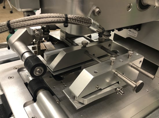
2. Swing Wedge Handle #2 in this will engage wedge with rollers. The wedge #4 should rest or …fit snug into the rollers #3 on both sides and should be centered.
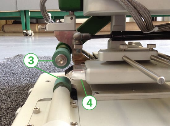
3. To center wedge between rollers, turn screw #5, this will fine tune wedge up and down. Only a 1/8 or 1/4 turn is necessary. Do not overturn. Move Pressure Roller Handle up and down slowly to check centering adjustment. Swing wedge handle in and out to ensure proper positioning.
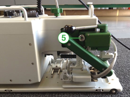
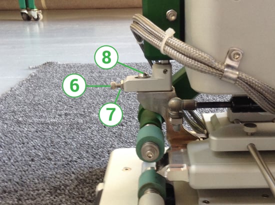
4. Adjustment Screw #6 will move wedge on a center axis left and right. Loosen Locking Screw #8 to make adjustment. Loosen Lock Nut #7, turn Adjustment Screw clockwise to bring right side of wedge in and counterclockwise to bring left side in. When adjusted properly, tighten Locking Screw and Lock Nut.
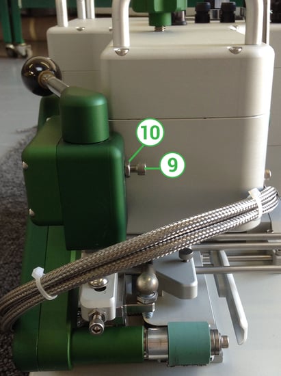
5. Wedge Stop Screw #9 will stop travel of wedge when positioning wedge in weld position. Loosen Locknut #10 , turn Adjustment Screw in or out to proper position. The edge of the wedge should fit snug and square into the rollers on each end.
Make a test weld before proceeding with job. Fine tuning your adjustments can be made while wedge is hot. Do not run Hot Wedge into Silicone Rollers without material in machine for extended periods, as it will distort the silicon.
NOTE: For thicker products (30mil and up) backing the wedge out may be necessary to allow room for material.The wedge should be replaced when honing and adjustment is no longer effective. If heater failure occurs after a period of time, the heaters may not be easily removed. The wedge and heater will most likely have to be replaced together.
-
Unplug machine and make sure wedge is cool.
-
Remove Hanger Bracket Screw #11 and remove Wedge Housing Assembly #14.
-
Unscrew and detach Heater Connector #12.
-
Remove both Wedge Screws #13, and remove wedge.
-
Install new wedge with Wedge Screws. Attach Heater Connector and re-attach Wedge.
-
Center Housing with Screw #11 and tighten.
-
Wedge alignment may be necessary, please refer to Wedge Adjustment Section.
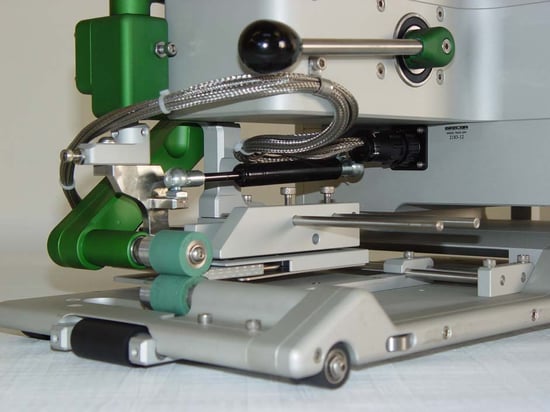
10.0 Wedge Installation
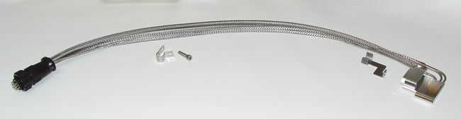
Install wedge on wedge mount arm along with lead bracket using two screws (note insert photo). Position heater wires properly on lead bracket and gently close tabs to secure.
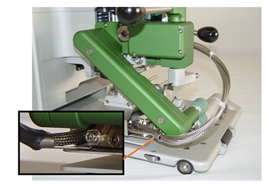
With wedge in engaged position, use zip ties to collect heater wires together. Note the wrap of heater wires around upper pinch roller arm and around back of Triad.
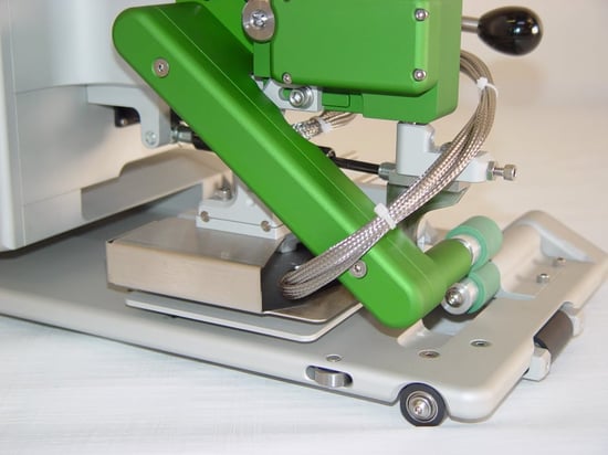
Using clip & screw, attach around heater wires and position to body of Triad. Do not fully tighten.
Electrically connect hot wedge to receptacle on body of Triad. When connected, make comfortable bend of heater wire and position properly in clip. Swing wedge in and out of welding position to make sure wrap around back of Triad is comfortable. When completed, tighten clip to secure.
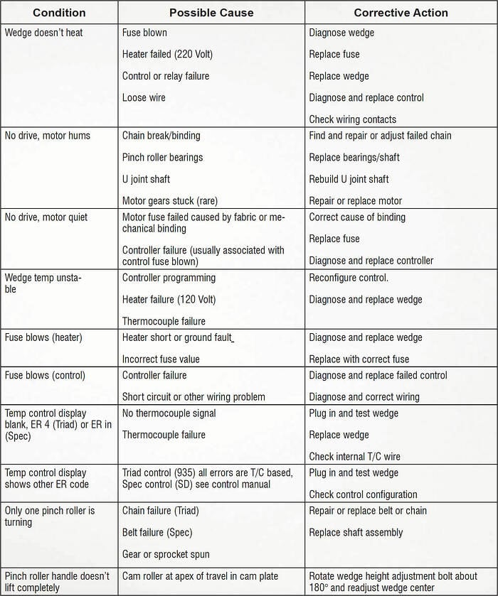
11.0 Troubleshooting