This instruction manual is intended to be a guide when operating the Boxmat PRO. To ensure optimal performance from your welder, please follow the recommendations and specifications precisely.
Table of Contents
- Chapter 1: Introduction
- Chapter 2: Health and Safety Regulations
- Chapter 3: Technical Data
- Chapter 4: Technical Specifications
- Chapter 5: Installation
- Chapter 6: Machine Operation
- Chapter 7: Description of HMI Panel Screen
- Chapter 8: Maintenance
- Chapter 9: Occupational and Safety Rules
- Chapter 10: Electrical Documentation
- Chapter 11: Pneumatic Documentation
- Chapter 12: Utilization and Machine Breaking
- Chapter 13: Enclosures
For more technical information regarding this machine call our Resolution Center at 1-855-888-WELD or email service@weldmaster.com.
1.0 Introduction
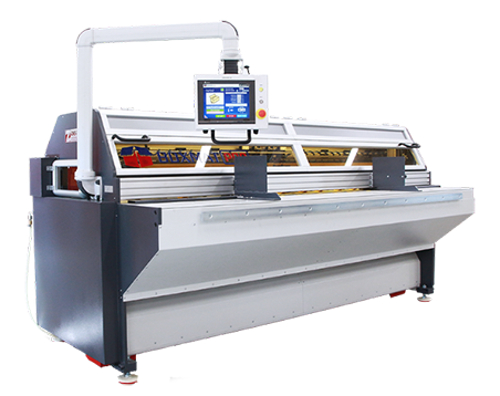
Boxmat PRO is the most modern and most versatile machine on the market and revolutionizes the production of corrugated packaging. Thanks to the automatic and tool-free change of settings on the HMI touch panel which can be changed within a few seconds, any product size may be programmed in standard, FEFCO types. PRO is ideal for the production of short series as well as for large, mass production. Slot-cutting, the removal of excess material, scoring, the removal of tongues of adhesive, as well as cutting the format to size, is carried out in one cycle without the need for additional attachment.
In ‘one go’, boxes of 3/5 layers of corrugated cardboard can be made. More than one box can be made from a suitably large format in just a single cycle.
The positions of the longitudinal tools are set using servo drives depending on the required size and thickness of the cardboard. Formats are centrally positioned for automatically positioned bumpers. A set of non-slip rollers and input-output shafts ensures precise and stable carton guidance throughout the entire cycle.
The innovative system applied, using circular knives, allows excess, or waste cardboard to be cut off from the remainder of the sheet. This solution facilitates the bi-directional correction of the size of the sheets and enables the sheets currently in production, to be cut to different sizes simultaneously, without having to be cut on a separate, peripheral device.
FEATURES:
- Notching, bi-directional scoring and cutting off waste in one cycle
- One integrated module for cutting, scoring and cutting off, eliminates production errors in multi-module machines
- Quick change of machine settings, on the touch panel, thanks to servo drives
- Possibility of longitudinal scoring which is a scoring function, transverse scoring and cutting sheets into smaller pieces - a crevice tool
- 4 knives + 4 longitudinal scoring wheels adjustable on the panel - a standard option
- An integrated punching system for cutting holes
- Ecological power and drive system as well as low power consumption
- Selection of styles, sizes, functions and the depths of the scores, using the touch screen
- Cardboard feeder with a reliable pick-up system
- Vibro-insulating legs preventing transmission of vibrations
- Secure and fast remote machine calibration and updating, thanks to remote internet connection
- Easy exchange of scoring wheels and cutting blades
![]() ATTENTION: Any intention of using this machine for any purpose other than as described in this manual must always be discussed with the manufacturer.
ATTENTION: Any intention of using this machine for any purpose other than as described in this manual must always be discussed with the manufacturer.
![]() ATTENTION: For the safety of all operators and other personnel, it is important that this manual is read and understood by all personnel; all instructions should be followed.
ATTENTION: For the safety of all operators and other personnel, it is important that this manual is read and understood by all personnel; all instructions should be followed.
![]() ATTENTION: It is highly recommended that each operator, once trained to use this machine, should append their name and signature to the form in this manual.
ATTENTION: It is highly recommended that each operator, once trained to use this machine, should append their name and signature to the form in this manual.
![]() ATTENTION: This machine was designed for use by able-bodied operators. Please contact the manufacturer for help and advice if it needs to be adjusted or modified for others.
ATTENTION: This machine was designed for use by able-bodied operators. Please contact the manufacturer for help and advice if it needs to be adjusted or modified for others.
2.0 Health and Safety Regulations, Signs and Labels
The health and safety of operators and of other personnel within the vicinity of this machine, is of paramount importance.
In order to use this machine safely, it is very important that this manual is read thoroughly by all personnel who intent to work with, or near the machine. All safety instructions should be adhered to, including the warning labels in the manual, as well as those displayed on the machine.
It is imperative that the purchaser be obliged to work out their own WORKSTATION INSTRUCTIONS for their machine operators, using the instructions in this service manual and the knowledge derived from the manufacturer's own experience of the technology of the product.
The ultimate, legal and financial responsibilities for all the potential events that may occur, due either to ignorance of this service manual or ignorance of Occupational Health and Safety regulations, lies with the purchaser. It is, therefore, ESSENTIAL to read and follow the safety instructions.
Warning Signs
![]() ATTENTION: Each operator MUST read the text of this service manual before undertaking any work with the machine.
ATTENTION: Each operator MUST read the text of this service manual before undertaking any work with the machine.
![]() ATTENTION: The purchaser is strongly advised to draw up their own WORKSTATION INSTRUCTIONS for the machine operators, on the basis of the text included in this service manual and the knowledge derived from their own production technology.
ATTENTION: The purchaser is strongly advised to draw up their own WORKSTATION INSTRUCTIONS for the machine operators, on the basis of the text included in this service manual and the knowledge derived from their own production technology.
 ATTENTION: UNDER NO CIRCUMSTANCES should the machine be operated by unqualified personnel. Machine operators must be familiar with Occupational Health and Safety regulations with special focus on the risks inherent in this machine. As a consequence of the aforesaid, documentation, approving completion of training and signed by the trained operator, should be issued.
![]() ATTENTION: The machine was not designed to be operated by disabled operators. If the need arises - and after prior consultation with the Manufacturer- the machine can be appropriately adjusted for disabled operators.
ATTENTION: The machine was not designed to be operated by disabled operators. If the need arises - and after prior consultation with the Manufacturer- the machine can be appropriately adjusted for disabled operators.
![]() ATTENTION: According to the manufacturer's recommendations, the machine should be installed in an industrial environment only.
ATTENTION: According to the manufacturer's recommendations, the machine should be installed in an industrial environment only.
![]() ATTENTION: Careless handling of the machine, during transport and/or relocation, may lead to severe injury or accidents.
ATTENTION: Careless handling of the machine, during transport and/or relocation, may lead to severe injury or accidents.
![]() ATTENTION: Periodical, adequate preventive inspection of the fire protection system should be carried out, in and around the machine. The purchaser is fully responsible for arranging to conduct such inspections.
ATTENTION: Periodical, adequate preventive inspection of the fire protection system should be carried out, in and around the machine. The purchaser is fully responsible for arranging to conduct such inspections.
![]() ATTENTION: A life threatening, high-power network voltage of 3 x 480V; 50...60 Hz is supplied to the machine. As a result, all servicing should be undertaken by appropriately qualified personnel only, as required by law.
ATTENTION: A life threatening, high-power network voltage of 3 x 480V; 50...60 Hz is supplied to the machine. As a result, all servicing should be undertaken by appropriately qualified personnel only, as required by law.
 ATTENTION: Work carried out in the feeding, cutting or bending zones within the systems, should be conducted by qualified personnel only, after taking all precautionary measures. In the above-mentioned zones, higher instances of potential body injury are possible.
 ATTENTION: The EMERGENCY STOP button is designed to be pressed at any time but especially when an emergency shutdown is urgently needed.
![]() ATTENTION: The area surrounding the machine should not be blocked by any objects, as this may result in personnel stumbling, sliding and falling which may lead to severe injury.
ATTENTION: The area surrounding the machine should not be blocked by any objects, as this may result in personnel stumbling, sliding and falling which may lead to severe injury.
![]() ATTENTION: The operator should always ensure that all doors, lids, shields and other protective devices are securely in place before the machine is started.
ATTENTION: The operator should always ensure that all doors, lids, shields and other protective devices are securely in place before the machine is started.
![]() ATTENTION: An operator must never climb onto the machine when it is in operation.
ATTENTION: An operator must never climb onto the machine when it is in operation.
![]() ATTENTION: The through-route of the corrugated board must NEVER be blocked by personnel or by any obstacle.
ATTENTION: The through-route of the corrugated board must NEVER be blocked by personnel or by any obstacle.
Prohibitory and Mandatory Signs
 UNDER NO CIRCUMSTANCES should the machine be operated by untrained personnel. The machine’s operators must be familiar with Occupational Health and Safety regulations with special focus on the risks inherent in this machine.
 ATTENTION: UNDER NO CIRCUMSTANCES should the machine be operated by unqualified personnel. Machine operators must be familiar with Occupational Health and Safety regulations.
 UNDER NO CIRCUMSTANCES should the machine be assembled, dismantled or transported by untrained personnel, nor by those unfamiliar with the safety regulations included in this service manual, since such activities may lead to an accident or to financial loss.
 UNDER NO CIRCUMSTANCES should servicing or maintenance be conducted, or preventive measures be taken, without fully disconnecting from the electrical supply.
 UNDER NO CIRCUMSTANCES should any of the sub- assemblies, such as the guide rollers, the cutting or scoring tools, be touched.
UNDER NO CIRCUMSTANCES should any measures be undertaken which could lead to a reduction in the machine’s safety status; this includes such measures as blocking master switches, removing guards or disconnecting sensors, etc.
UNDER NO CIRCUMSTANCES should an operator climb onto the machine during the loading procedure or during its regular work cycle.
 UNDER NO CIRCUMSTANCES should any potential fire, near the machine, be extinguished with water. Use only licensed, sophisticated, firefighting agents and fire-hazard protection products.
 UNDER NO CIRCUMSTANCES should the guards be removed during the machine’s work cycle.
 UNDER NO CIRCUMSTANCES should the machine be sprayed with water during its regular work cycle or when it is idle.
 UNDER NO CIRCUMSTANCES should any maintenance tasks be conducted while the machine is in operation.
 UNDER NO CIRCUMSTANCES should any oil, solvent or any other caustic or toxic substances be poured out, either in or near the machine.
 UNDER NO CIRCUMSTANCES should mobile phones be used in the immediate vicinity of the machine.
 UNDER NO CIRCUMSTANCES should any naked flame be used in the immediate vicinity of the machine.
 UNDER NO CIRCUMSTANCES should cigarettes be smoked in the immediate vicinity of the machine.
 UNDER NO CIRCUMSTANCES should alcohol be drunk in the immediate vicinity of the machine, nor should personnel, under the influence of alcohol, operate the machine.
 UNDER NO CIRCUMSTANCES should personnel eat in the immediate vicinity of the machine.
 IT IS STRONGLY ADVISED that each person, assigned to operate the machine, be fully trained. The scope of training should cover operation of the machine, as well as Occupational Health and Safety regulations, with special focus on the risks inherent in the machine.
 IT IS HIGHLY RECOMMENDED that ALL covers and guards, designed for the machine, be used.
 IT IS ESSENTIAL that in the event of any accident involving the operator, or any machine failure, both should be reported to the management promptly.
 IT IS ESSENTIAL to wear safe, close-fitting, workwear to reduce the possibility of being snagged or pulled into the machine.
 IT IS ESSENTIAL to wear protective gloves while operating the machine.
 IT IS ESSENTIAL to wear anti-slip working footwear.
 Hearing protection must be worn in this area.
 IT IS ESSENTIAL that long hair be tied back in such a way as to reduce the risk of being snagged or pulled into the machine; operators must wear either appropriate hair covering or wear their hair tied up.
 IT IS ESSENTIAL to keep the floor around the machine clean and clear of any paper, board or other waste.
 IT IS REQUIRED that all machine operators are well-trained personnel, acquainted with Occupational Health and Safety regulations; they should also be familiar with all hazardous situations likely to occur in the operation of sophisticated machines of this complexity.
IT IS ESSENTIAL to use the emergency stop switch button whenever the operator's life or health is at risk.
IT IS ESSENTIAL to disconnect the machine from the power supply whenever servicing, maintenance or preventive activities are underway.
 During packing, unpacking and transportation, special measures should be taken, in order to prevent the machine from tipping over.
4.0 Technical Specifications
- The Boxmat Pro machine consists of the main body, containing all the electrical and mechanical components, and movable work table. The main body is based on a metal frame ensuring the adequate level of stability. The work table is designed to assist the operators feeding the corrugated material through the machine.
- The corrugated blanks are carried through the machine by a series of rollers and wheels driven by servo-drives. In a similar way the slotting beam is propelled by a servo drives.
- Behind the slotting/scoring beam is the innovative system of rotary tools that enable the operator to cut off excess board and eject them without any cuts or scores enabling them to be re-used for smaller boxes. This also allows oversized blanks to be trimmed to size as they pass through the machine instead of having to trim on another, separate machine.
- It also allows the production of two boxes at one time (with Multi-production option), if box size and sheet size are suitable by attaching a central knife.
- The slots are punched out by a system of blades attached to the scoring beam.
- The slotting blades are automatically moved to the correct positions by asynchronous motors driven by the inverter and encoder, once the dimensions is entered into the touch screen.
- The left hand guide is positioned automatically and, once a board blank is positioned against it, the right hand guide can be slid up to it to allow the blank to pass through the machine without any twisting.
- The machine is equipped with a full set of covers and guards to protect operators from the moving blades and knives. To comply with all European safety regulations, the machine will not operate if these are not all in place and an appropriate error message will be displayed on the screen.
The manufacturer will ensure that the machine is appropriately packaged for transport. The type and strength of packaging are adapted to the distance and means of transport used, as well with regard to the potential risks associated with the means of transport used. The Manufacturer suggests that Recipients use the Manufacturer's means of transport and service personnel.
Storage of an unused machine does not imply any requirements other than a suitable storage environment. Warehousing must provide sufficient protection against atmospheric agents and be dry, with an acceptable humidity level below 70%. The storage temperature should be between 5 ºC and 40 ºC.
Adequate anti-corrosion protection should be ensured, especially for metal parts which, for technical reasons, have not been painted or protected against corrosion.
If the machine is delivered in a crate and/or covered with film-wrap that creates an anti-corrosive atmosphere, the machine should remain in the same, throughout the entire storage period.
To protect against moisture, it is recommended that the machine is not stored on the floor of the warehouse but on pallets, in order to keep it lifted off the floor.

This box maker should be stored vertically in a dry and well ventilated room. The machine is sensitive to vibration, shock, violent jolts and long-lasting tilts. Even if it is dropped from a relatively insignificant height this may lead to its permanent and irreversible damage.
The above provisions are intended to make all persons and services, who have contact with this device, aware of its high sensitivity to any impactful stimuli and, at the same time, aware also, that no claims, arising from such permanent damage, as described above, will be considered as a valid complaint.
For further advice or information, please contact the manufacturer’s service technicians.
Transport
 UNDER NO CIRCUMSTANCES should the machine be assembled, dismantled or transported in any way by unqualified personnel or those unfamiliar with the safety and care information included in this manual. Failure to comply with this basic rule may lead to accidental damage or injury not covered by the manufacturer’s warranty or liability.
- The entity responsible for transporting and installing the machine at the Ordering Party's plant should be determined at the contract signing stage, however at the latest, after the technical acceptance of the machine at the Manufacturer's plant and before being issued to the Ordering Party.
- Due to the nature of the device, the Manufacturer suggests that the Recipients use the Manufacturer's means of transport and service personnel.
- The machine should be moved using lifting devices such as cranes, forklift trucks or pallet trucks, all of which should have sufficient lifting capacity for the purpose of safe transportation. The persons operating them should have the required permits and the training, as required by law.
- The correct mode of transportation for BOXMAT PRO machines is presented below.
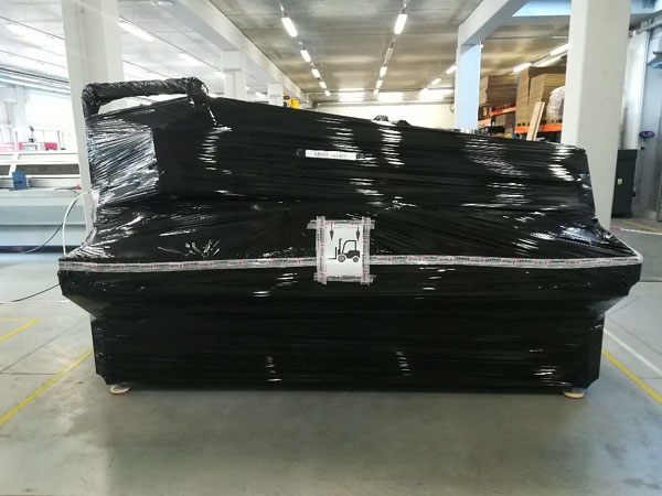
Fig. 2. The location for lifting the machine is indicated by the pictogram (Fig. 2 -1)
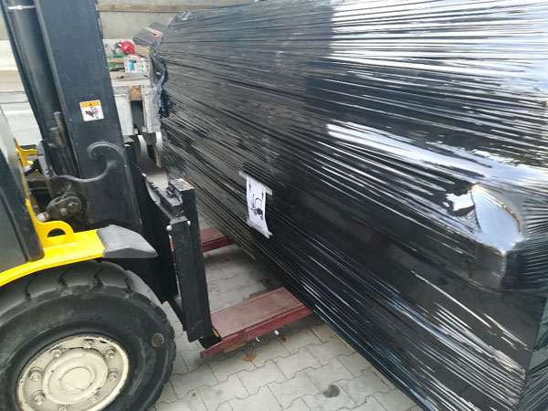
Fig. 3. The correct transportation of the machine using a forklift truck
It is forbidden to lift the BOXMAT PRO machine where so indicated by pictograms; the drawing below refers.
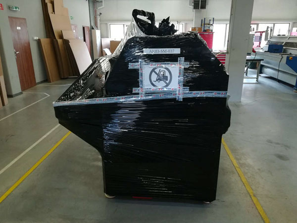
Fig. 4. It is forbidden to lift the BOXMAT PRO machine by its side walls, using a forklift truck.
![]() ATTENTION: Failure to comply with the above pictograms and methods of assembly, may result in damage to the machine's structure and components.
ATTENTION: Failure to comply with the above pictograms and methods of assembly, may result in damage to the machine's structure and components.
![]() ATTENTION: Machine must be transported vertically.
ATTENTION: Machine must be transported vertically.
It is essential that the machine, and all parts and accessories, must be packaged safely and securely. Suitable protective wrapping, pallets and/or crates should be supplied to ensure that the machine and all peripheral parts and accessories arrive for installation safely and undamaged. It is strongly advised to allow the manufacturer to undertake all these tasks to ensure a safe and efficient delivery and installation.
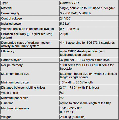
As far as transport procedure is concerned the machine's weight (c. 2800 kg - 6200 lb.) must be taken into account.
![]() ATTENTION: Careless handling of the machine during transport and/or relocation may lead to severe accidents or injuries.
ATTENTION: Careless handling of the machine during transport and/or relocation may lead to severe accidents or injuries.
Installation
Installation of the machine at the workplace, is effected by the Ordering Party's personnel, once the contents of these operating instructions and the Manufacturer's services have become familiar to- and have been agreed to- by the Ordering Party’s personnel. The correct setting of the printer is important as a precondition for its optimal functioning and for the comfort and safety of the operators.
Preparation of the location for the machine, the availability and parameters of electrical, pneumatic and ventilation connections, as well as the preparation of the specific design and acceptance requirements, needed to facilitate operation of the machine, is the responsibility of the Ordering Party.
The Manufacturer will provide the necessary guidance and information to assist the Ordering Party in this regard.
After delivering the machine to its designated location, it should be unpacked and leveled. Its technical condition should then be checked and any damage caused in transport, should be rectified.
![]() ATTENTION: The floor on which the machine is to be placed must have sufficient structural strength to support the weight of the machine and any vibration generated by the normal process of manufacturing boxes. It should also be noted that the majority of the weight of the machine is concentrated at the feet.
ATTENTION: The floor on which the machine is to be placed must have sufficient structural strength to support the weight of the machine and any vibration generated by the normal process of manufacturing boxes. It should also be noted that the majority of the weight of the machine is concentrated at the feet.
![]() ATTENTION: Once the machine is leveled it should not be moved without repeating the leveling process.
ATTENTION: Once the machine is leveled it should not be moved without repeating the leveling process.
The most optimal flooring is made of plain concrete of sufficient depth and coated with a thin layer of non-conducting material.
The foundation on which the machine is placed should be architecturally compliant with the building standards and safety rules fulfilling the requirements of depth, strength and level.
The Buyer is the only person responsible for preparation of base on which the machine is supposed to be installed.
![]() ATTENTION: If the assembly and set-up procedures are conducted individually by the purchaser, they should be performed due to the instructions included in this service manual and/or according to the instructions provided by the manufacturer during the technical acceptance procedure.
ATTENTION: If the assembly and set-up procedures are conducted individually by the purchaser, they should be performed due to the instructions included in this service manual and/or according to the instructions provided by the manufacturer during the technical acceptance procedure.
Use the screws in the machine feet to level the frame. (The sides of the machine's body are the reference plane for level).
![]() ATTENTION: After each change position the machine, check the gap between the upper and lower slotting knives. On the entire length of the upper slotting blades, from the front and back side, the gap should not be less than 0.004 inch.
ATTENTION: After each change position the machine, check the gap between the upper and lower slotting knives. On the entire length of the upper slotting blades, from the front and back side, the gap should not be less than 0.004 inch.
When the machine is leveled, then the work tables should be assembled and placed at the front and rear of the machine (tables are available on demand). Once both work tables are delivered, they should be leveled to the machine.
Work Conditions
GENERAL INFORMATION
![]() ATTENTION: It is the manufacturer’s recommendation, that the machine should be installed in an industrial environment only.
ATTENTION: It is the manufacturer’s recommendation, that the machine should be installed in an industrial environment only.
As written and described within this technical manual, this machine has been designed and manufactured to be used in an industrial environment for the conversion of corrugated fiberboard into a range of cartons and, as such, this machine must be operated within the health and safety regulations associated with the industrial box-making environment.
This machine must not be operated in a potentially explosive atmosphere, in an atmosphere with a high level of pollution, high humidity, high temperatures or in aggressive, or corrosive, fumes.
Due to the electronics and sensors within this machine, it should be used in temperatures from +15°C to +35°C and in a relative humidity ranging from 35% to 85%. Atmospheric humidity condensation, or any potentially aggressive agents, should be avoided.
Temperature changes within the operating environment should not exceed 10°C and the relative humidity should not vary by more than 10%.
![]() ATTENTION: If there are significant temperature and humidity differences between the delivery process and the installation site, the machine should be stored and acclimatized in the site where it is to be operated for 24 hours before starting up.
ATTENTION: If there are significant temperature and humidity differences between the delivery process and the installation site, the machine should be stored and acclimatized in the site where it is to be operated for 24 hours before starting up.
LIGHTING
The criterion for the minimum level of lighting indicates that the acceptable lighting on a horizontal working plane, in rooms where personnel attend for a long time, regardless of what visual tasks are performed, should be 300 lx.
Where, however, there is a degree of visual difficulty greater than average, resulting in difficulties in working, the requirement pertains to ensure higher viewing comfort; this also applies where employees are mostly people over 40 years of age. With this in mind, the level of intensity in the lighting should then be higher than the minimum permissible level of 500 lx.
5.4.3. NOISE
The device is the source of the noise intensity above 85dB requiring use of plant protection personnel.
 Hearing protection must be worn in this area!
We note that all environment have their own noise emissions, which can effectively influence the levels of noise issued by the machine during operation, especially in various technological systems.
Power Supply Parameters
ELECTRIC SUPPLY
The machine must be connected to a power supply of 3 x 480 VAC; 50/60 Hz; (3P+N+PE), equipped with overcurrent protection.
The Buyer's installation must provide shock protection in accordance with PN-EN 60204-1:2018-12.
COMPRESSED-AIR SYSTEM
The machine uses air pressure ranging from 6-8bar / 85-110 psi.
The filtered impurities are less than 20 µm, to comply with ISO8573-1 4-4-4 standards.
6.0 Machine Operation
Assuming that all conditions for the installation and activities described in the previous chapter have been met and successfully carried out, preparations can begin for the first start-up of the machine, in production conditions at the Contracting Party's plant.
Assuming that all conditions for the installation and activities described in the previous chapter have been met and successfully carried out, preparations can begin for the first start-up of the machine, in production conditions at the Contracting Party's plant.
![]() ATTENTION: Initially, the machine should be started up under the supervision of the manufacturer’s agents.
ATTENTION: Initially, the machine should be started up under the supervision of the manufacturer’s agents.
The Service Conditions must be read and understood before starting the machine.
SERVICE CONDITIONS – GENERAL GUIDELINES AND PROCEDURES
To ensure correct machine operation, all adjustments and settings must be carried out by the manufacturer's trained technicians, once the machine has been assembled and installed and the initial start-up procedures have been implemented. Corrugated material for testing the machine should be made available by the Buyer.
Before using the machine, that is, prior to its first start-up, the Contracting Party has the absolute obligation to train those employees who will be its future operators. Moreover, due to the different work cycles carried out by our machines, in various industrial environments, the Recipient has the absolute obligation to create a clear and transparent workplace instruction manual for the device, adapted to its own production cycles.
![]() UNDER NO CIRCUMSTANCES should the machine be operated by unqualified personnel. The machine operators must be familiar with the occupational health and safety rules, with the focus on giving special consideration to the risk created by using this machine.
UNDER NO CIRCUMSTANCES should the machine be operated by unqualified personnel. The machine operators must be familiar with the occupational health and safety rules, with the focus on giving special consideration to the risk created by using this machine.
 ATTENTION: The Recipient, or a person authorized by him/her on the basis of these operating instructions and the characteristics of his/her own production technology, has the absolute obligation to compile a MACHINE-BASED INSTRUCTION MANUAL for the employees.
 IT IS STRONGLY RECOMMENDED to instruct each person assigned to work with, or near, this machine not only in the operating of the machine but also in the occupational health and safety rules associated with operating the machine.
 The setting and checking procedure, implemented prior to using this machine, must only be performed by trained and authorized personnel.
BEFORE USING THE MACHINE IT IS STRONGLY RECOMMENDED TO CHECK THE FOLLOWING:
- the effectiveness of protection against electric shock;
- the supply voltage;
- value and phase compliance;
- the emergency buttons (safety switches - EMERGENCY STOP) if necessary, unlock by turning clockwise;
- the magnetic safety sensors of the covers and side windows;
- the security locks are, in fact, locked;
![]() ATTENTION: Any maintenance work or changing of tools etc., that requires the machine to be operated with covers open, must only be carried out by trained and competent personnel and must be completed as quickly as possible before the covers are closed and full safety status is restored.
ATTENTION: Any maintenance work or changing of tools etc., that requires the machine to be operated with covers open, must only be carried out by trained and competent personnel and must be completed as quickly as possible before the covers are closed and full safety status is restored.
![]() ATTENTION: All switch boxes, covers and guards must be closed before attempting to use the machine and must remain closed during use.
ATTENTION: All switch boxes, covers and guards must be closed before attempting to use the machine and must remain closed during use.
It is strictly forbidden to operate the machine with any safety switches or other safety devices defeated or altered in any way. All these devices are fitted to protect the safety of the operator and other personnel. It is recommended that all such devices are checked and tested regularly to confirm that they are all operating correctly.
Each machine operator should be familiarized with all the safety features and devices associated with this machine.
 IT IS STRICTLY FORBIDDEN to remove any covers or guards while the machine is in operation.
 IT IS STRONGLY RECOMMENDED TO attach and close ALL covers and guards designed for the machine.
In the area around the machine, and up to 1.5m, all obstacles must be removed and the area must be clean and appropriately lit. Particular care should be taken when Fork Lift Trucks are fetching and removing materials and cartons.
The area in close vicinity to the machine should be clean and cleared of impurities such as oil, dust and dirt in order to reduce to the minimum the risk of a slip, trip or fall.
 ATTENTION: When the machine is in operation the area surrounding the machine should not be blocked as it may cause a slip, trip or fall.
 UNDER NO CIRCUMSTANCES should any oil, solvents or other caustic or toxic liquids be poured out in the close vicinity to the machine.
 IT IS THEREFORE ORDERED to keep the floor around the machine clean and clear.
The machine controls, indicators, flexible conductors, pipes or shafts should not be used as handles. Any unintentional displacement of these machine parts may cause accidental and unintentional activation or changes to the machine working parameters and, in extreme situations, may lead to the machine failure or break- down.
 IT IS ESSENTIAL that any accident involving the operator, or any machine failure, should be promptly reported to the management.
The qualified machine operators should be equipped with the regular working clothing, protective gloves and anti-slip, safety footwear.
Since the basic risks to the machine operators are moving rollers, wheels and shafts, the machine should not be operated by personnel wearing loose clothing or long and loose hair.
 IT IS ESSENTIAL to wear the suitable working clothing reducing to the minimum the possibility of being snagged or pulled into the machine.
 IT IS ESSENTIAL to wear protective gloves while operating the machine and handling cardboard.
 IT IS ESSENTIAL to wear anti-slip working footwear.
Hearing protection must be worn in this area!
 IT IS ESSENTIAL to secure the operator’s hair in such a way to reduce to the minimum the risk of being snagged or pulled into the machine.
Controls and Indicators Available for Operator
In the machine presented, all handling elements are located directly on its construction body, or on the control panel. Before using the machine, all personnel operating the machine should familiarize themselves with the location of these elements and the functions they control.
The handling and control elements of the machine which are available to the operator include:
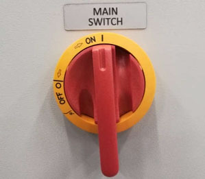
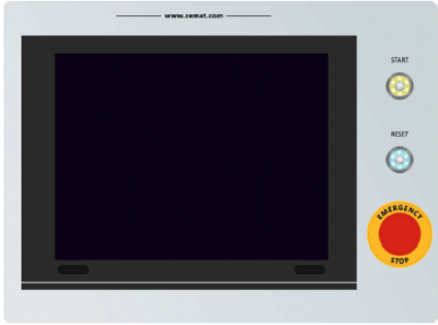
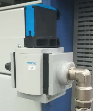
Fig.5. MAIN SWITCH Fig.6. CONTROL PANEL Fig. 7 COMPRESSED AIR TERMINAL
- MAIN SWITCH - the switch installed on the switch box doors (Fig.5), is designed to switch the electrical supply on and off. When it is turned to the 1 position it means that the machine is ON, when it is turned to the 0 position, it means that the machine is switched OFF.
- HMI panel – a touch-sensitive screen which can be found on the control panel (Fig.6), it is designed to programming and control the machine.
- START – This green button, when lit, indicates that the machine is ready for work (Fig.6)
- RESET – a blue button used to restart the control system and the machine’s safety system and alarms after an error (Fig.6).
- EMERGENCY STOP - a mushroom-headed button for the immediate shutdown of the entire machine, in the event of any failure or accident. Buttons are located on the operator's panel (Fig.6) and to the rear and side of the machine.
-
Compressed air terminal (Fig.7);
-
The manually operated compressed air shut-off valve (in order to open the valve - turn it to the left and set to ON position; a turn to the right - the OFF position - the valve is closed);
Positioning of Right Guide and Input Stops
ADJUSTING THE POSITION OF THE RIGHT LIMITER AND THE ENTRY BUMPERS
![]() ATTENTION! Regulation should be conducted after selection of style, entering the cardboard dimensions and automatic setting of left guide.
ATTENTION! Regulation should be conducted after selection of style, entering the cardboard dimensions and automatic setting of left guide.
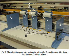
- Place the blank on the table
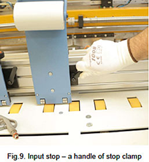
- Undo handles of the input stops (Fig.9).
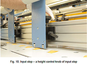
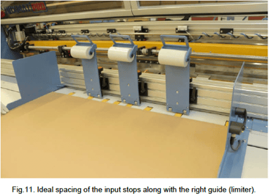
- Lift up the input stops gently and slide apart two of them towards the ends of board and the third one should be placed in the center and over the roller (Fig.11).
- Tighten up the orange handles of the input stops (Fig.9).
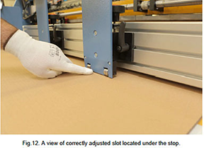
- Using the knob (Fig. 10) set the gap under each bumper so that it is possible to insert one carton into it; ensure, however, that it is not possible to insert two cartons (Fig.12).
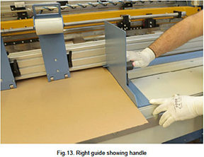
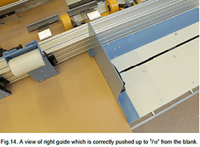
- Set the right stop with the help of the hand grip (Fig.13) so that it almost sticks to the mat; leave 1/16” of slack so that the mats do not jam between the stops (Fig.14).
Connection to a Power Source
- Check the area around the machine. It is designed to work in a clean and neat environment without any waste or obstacles that could adversely influence on its regular working activity.
- Prepare the corrugated blanks, ready for production.
- If required by the production cycle provided by the user, place containers for waste and ready-printed cartons in a suitable place, near the machine.
- Check that all covers and guards are in place and that all doors are closed – it is strictly forbidden to perform work with open covers or missing guards as this will trigger the proximity sensors and prevent the machine from working.
- Check that the EMERGENCY STOP push-button on the control panel is in the correct position. In order to reset it turn the mushroom-headed push- button clockwise.
- Connect the electrical power supply to the machine (put the plug into the power supply socket and/or switch on) and the compressed air system by connecting the air hose to the terminal and switching on the compressor.
- Check that the pneumatic supply is between 85psi/6bar and 110psi/8bar.
- Turn the MAIN SWITCH installed in the machine side casing, to the 1 / ON position.
- Due to standard procedure when the machine is switched on, an error message such as ALARM: NOT READY; EMERGENCY STOP should be found on the HMI touch panel. In order to put the machine in motion press START button. As a result, the test of alarm systems and the drives shall be put into operation. When the START button flashes green, it means that the machine enters a stand-by mode and it is ready for work.
- When the TEST key is displayed on the touch-sensitive display panel, press it and as a result the rollers transporting cardboards will be put in rotation test along with a knife which is supposed to perform a down/up movement test (procedures last about 5 seconds).
- If all procedures end up successfully, the machine is ready for work – the main window should be displayed on the HMI panel.
![]() ATTENTION: Covers must always be closed or the machine will not work.
ATTENTION: Covers must always be closed or the machine will not work.
![]() ATTENTION: the EMERGENCY STOP button is designed to be pressed at any time especially when an emergency shut- down is promptly needed.
ATTENTION: the EMERGENCY STOP button is designed to be pressed at any time especially when an emergency shut- down is promptly needed.
![]() ATTENTION! In case the error message can still be seen on the display after pressing the START button, go to ALARMS, ERROR MESSAGES and FAILURES shown in the technical documentation.
ATTENTION! In case the error message can still be seen on the display after pressing the START button, go to ALARMS, ERROR MESSAGES and FAILURES shown in the technical documentation.
Disconnection
The following switch-off procedure should always be implemented when production is completed:
- Turn the MAIN SWITCH to the position 0-OFF – this means that the machine is switched off.
- Clear the working environment around the machine.
- If the machine is being shut down for a longer period – i.e. the weekend - The electrical power supply and the compressed air should be disconnected.
7.0 Description of HMI Panel Screen
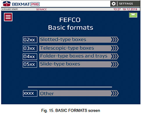
Home - Choice of Box Design
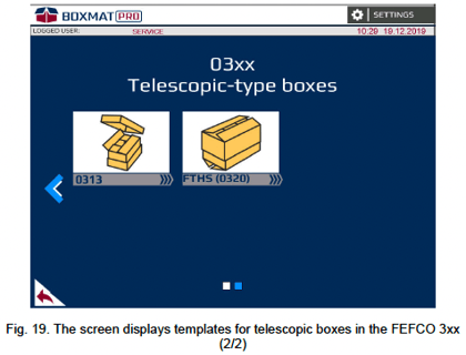
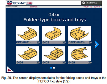
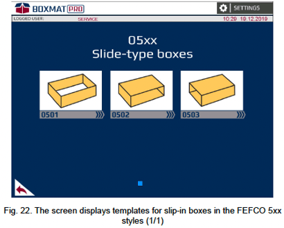
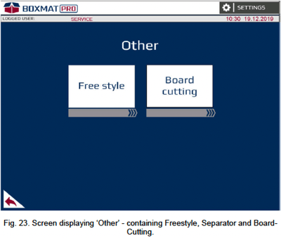
On the main screen, are the basic formats of the FEFCO styles available. First, select the style or select ‘Other’ if a Free Style box is to be designed.
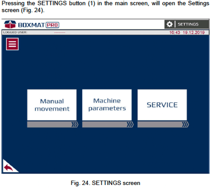
- SETTINGS - the button opens a SETTINGS screen (page 51). On this screen, three further screens can be selected:
- Manual Movement - options available on the Manual Movements screens which allow all moving parts, available in the machine, to be moved manually.
- Service - options available in the Service screens contain statistical information on the machine’s operation and advanced parameters of the machine's operation.
-
MENU - the button opens a screen showing the following features: LOGGING IN, RECIPES, STATISTIC and LANGUAGE settings.
-
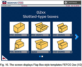
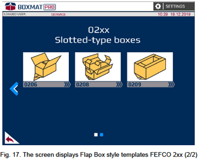
SLOTTED-TYPE BOXES (flap boxes) - the button opens a screen containing templates for flap boxes in FEFCO styles (Fig. 16, Fig. 17).

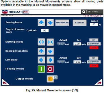
 moves the scoring beam upwards
 moves the scoring beam downwards;
 When the Up Arrow button displays yellow, it indicates that the scoring/slotting beam is in the top position ready for starting.
14. REFERENCING - the button sets the scoring beam with slotting knives in the top position for starting.
15. FAST CUT - the button starts one full cycle of the scoring/slotting beam at setup speed- value 0% - without scoring between the slots;
- value 100% - max scoring depth between the slots;
17.  these buttons change the position of the slotting knives. Press and hold to move:
 the slotting knives move apart slowly.
 the slotting knives move closer slowly.
The position of the slotting knives is measured as the distance fromthe point of the left knife to the point of the right knife. The knives move evenly toward or away from the center of the machine. Spacing of the blades can range from 2 1/2” to 78 1/2“.
When one of the buttons displays a yellow arrow, it indicates that the slotting knives have travelled as far as possible.
18. Actual - the field displays the current distance between the slotting knives.
19. Set field - enter the distance at which the slotting knives should be spaced.
20. Set button - starts the slotting knives' movement to a position as entered in the Set field (19).
21. Calibration button – opens a window to enter the actual measurement between the knives. This will update the ‘Actual’ field.
Opening of the calibration window is only possible after entering Password 7415
22. STOP – the button stops slotting knives movement
23. Board Pass Motion ![]() Press and hold to move the corrugated sheet in or out of the machine. Press
Press and hold to move the corrugated sheet in or out of the machine. Press ![]() for forward and
for forward and ![]() for reverse.
for reverse.
24. Board Guide ![]() Press and hold these buttons to change the position of the left, automatic, board guide.
Press and hold these buttons to change the position of the left, automatic, board guide.
The position of the left guide is measured as the distance from the inner wall of the guide to the center of the machine. It is possible to set the guide within the range 1 3/4” to 47”.
When one of the buttons displays a yellow arrow, it indicates that the left guide is in the extreme position.
25. Actual Position - the field displays the current position of the board guide.
26. Set - the field in which it is possible to enter the position at which the left board guide is to be set.
27. Set - this button moves the left guide to the position in the ‘Set’ field. (26).
28. Calibration button – opens a window to enter the actual distance from the center of the machine to the left guide. This will update the ‘Actual’ field (25).
Opening of the calibration window is only possible after entering Password 7415.
29. STOP – the button stops the left guide movement
30. Feeding Rolls: ![]() - these buttons are used to start or stop the feed rollers.
- these buttons are used to start or stop the feed rollers.
31. ![]() this button returns to the previous screen (Fig. 24).
this button returns to the previous screen (Fig. 24).
32. ![]() this button leads to the next screen (Fig.26).
this button leads to the next screen (Fig.26).
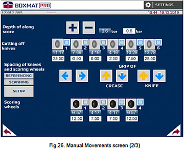
33. + - these buttons change the depth of the scores along the box by adjusting the pressure on the rolls. Pressing the button changes the pressure setting by 0.1 bar.:
- + increases the pressure;
- - reduces the pressure.
It is possible to set pressure within the range 0 to 3 bar.
The pressure can never reach a value greater than the supply pressure to the machine.
34. The field displaying the actual pressure applied to the scoring wheels.
35. The field displaying the set pressure applied to the scoring wheels. In this field, it is possible to enter the pressure value. By pressing the Enter button on the keyboard, the pressure will be updated.
36. Along cutting off knives - These graphics show the active lengthwise cutting- off knives (trim-to-width). Pressing on the picture will lift or lower the corresponding knife. Lowering of the knife is indicated by a green "tick" ![]() .
.
The machine can accommodate 4, 6 or 8 knives. The maximum number of knives used depends on any additional options of the machine.
37. The fields display the actual position of each rotary, lengthwise knife.
The position of each lengthwise cutting knife is measured as the distance from the blade to the center of the machine. It is possible to set the knives within the range 1 3/4” to 47”.
38. Fields displaying the pre-determined position of each lengthwise knife. In these fields, it is possible to enter the position at which each knife is to be set from the center.
The knives should be spaced in the same order as presented in the graphics, otherwise the message "NOT POSSIBLE TO SET UP ALONG KNIVES [KNIFE NUMBER ]” will be displayed.
Spacing of knives and scoring wheels ![]() these buttons change the position of the tool holder, that is, the scoring wheels and the longitudinal knives:
these buttons change the position of the tool holder, that is, the scoring wheels and the longitudinal knives:
 moves the holder to the left;
 moves the gripper to the right.
![]() these buttons lock or release the scoring wheels gripper pin:
these buttons lock or release the scoring wheels gripper pin:
 unlocks the gripper pin;
 locks the gripper pin.
An arrow in yellow indicates the pin's position ![]() pin locked,
pin locked, ![]() pin unlocked.
pin unlocked.
41. ![]() these buttons lock or release the longitudinal knives gripper pin:
these buttons lock or release the longitudinal knives gripper pin:
- unlocks the gripper pin;
- locks the gripper pin.
42. REFERENCING - this button moves the tool holder to his initial position.
When REFERENCING procedure is active backlight of the push button is on.
43. SCANNING - this button moves the scanner (tool holder) over the tools to define their actual positions and to check their quantities.
When SCANNING procedure is active backlight of the push button is on.
44. SETUP - this button moves the longitudinal cutting knives and scoring wheels to their pre-set positions as entered in the setup fields.
When SETUP procedure is active backlight of the push button is on.
45. Graphic drawings representing active scoring wheels. Pressing on the graphic drawing lifts or lowers the corresponding scoring wheels. Lowering the roller is indicated by a green "tick" ![]()
The machine can accommodate 4, 6 or 8 scoring wheels.
46. The fields display the current position of each scoring wheel.
The position of the scoring wheel is measured as the distance from the apex of the roller-or the middle of the roller when there are two pins - to the center of the machine. It is possible to set the rolls within the range 1” to 47”.
47. These fields display the pre-determined position of each scoring wheel. In these fields, it is possible to enter the position at which each roller is to be set.
The rollers should be spaced in the same order as presented in the graphics, otherwise the message "Incorrect data for the scores" will be displayed.
48. ![]() - this button returns to the previous screen (Fig. 25).
- this button returns to the previous screen (Fig. 25).
49. ![]() - this button leads to the next screen (Fig.27).
- this button leads to the next screen (Fig.27).
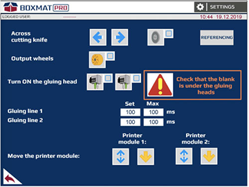
Fig.27. Manual Movements screen (3/3)
51. The graphic shows the transverse cutting knife. Pressing on the picture will lift or lower the knife. The lowering of the knife is indicated by a green "tick" ![]() .
.
52. REFERENCING - this button moves the across cutting knife to the home position.
When REFERENCING procedure is active backlight of the push button is on.
53. Output Wheels - The graphic shows the non-crush roller. Pressing on the picture lifts or lowers all the exit rollers. Lowering the rollers is signaled by a green "tick" ![]() .
.
54. The graphic shows two the gluing head. Pressing on the picture will open the gluing head (option).
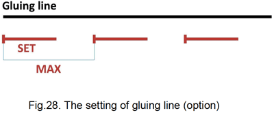
55. Gluing line 1 – Set – Opening time of the gluing head for the gluing line 1 (Fig.28) (option).
56. Gluing line 1 – MAX – Cycle time of the gluing head for the gluing line 1 (Fig.28) (option).
57. Gluing line 2 – Set - Opening time of the gluing head for the gluing line 2 (Fig.28) (option).
58. Gluing line 2 – MAX – Cycle time of the gluing head for the gluing line 2 (Fig.28) (option).
59. Move the printer module 1 (option):
 lift up/down the printer module 1
 or
or  indicates the position of printer module 1 Move the printer module 2 (option):
Move the printer module 2 (option):
- lift up/down the printer module 2
- or indicates the position of printer module 2
 - this button returns to the previous screen (Fig.26).
Machine Parameters Screens
The options available in the Machine Parameters screens are basic machine settings such as machine tool positions, velocity of individual sub-assemblies and so forth.

Fig. 29. The Machine Parameters’ screen (1/5)
62. Graphics showing active, along cutting knives. Pressing on the graphic element changes the orientation of the corresponding knife:
- a green "tick"
 indicates that the knife's orientation is to the left or right of the fixing as viewed from the front of the machine (Fig. 30– A,B).
If the operator changes the position of a tool, i.e. from the left side to the right, then this change MUST be entered into the machine parameters.
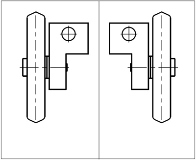
Fig. 30. An example of tool orientation on the basis of scoring wheels: A - to the left of the fixing as viewed from the front of the machine, B - to the right of the fixing as viewed from the front of the machine.
63. Rotary knives / razor blade knives - This parameter describes the type of knives mounted on the machine
The operator must always enter this change into the parameter if the machine’s knives have been changed from one type to the other.
64. Graphics representing active scoring wheels. Pressing on the graphic image changes the orientation of the corresponding roll:
- a green "tick" indicates that the roller is to the left or right of the fixing when viewed from the front of the machine (Fig. 30 – A,B).
The operator must always enter this change into the parameter if the machine’s scoring wheels have been changed from one side to the other.
65. Scoring wheels type 1 / type 2 - This parameter describes the type of scoring wheels mounted on the machine
The operator must always enter this change into the parameter if the machine’s scoring wheels have been changed from one type to the other.
66. ![]() - this button returns to the previous (Fig. 24).
- this button returns to the previous (Fig. 24).
67. ![]() - this button leads to the next screen (Fig. 31).
- this button leads to the next screen (Fig. 31).
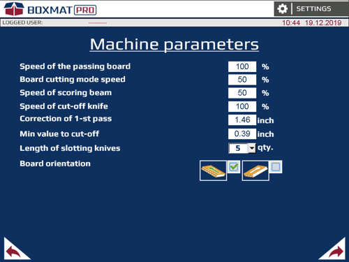
68. Speed of the passing board – speed of the board in the FEFCO or Free Style cycle.
69. Board cutting mode speed – speed of the board in board cutting mode
70. Speed of scoring beam – speed of the slotting/scoring beam in the cycle
71. Speed of cut-off knife – speed of the across cutting knife in the cycle
72. Correction of the 1st pass – this parameter will affect the length of the first panel of a box. If any maintenance has taken place, this parameter may need to be changed.
73. Min value to cut-off – set the min value to be cut-off by the length from oversized blank
74. Length of slotting knives – number of slotting knives mounted on the machine for every side
75. Board orientation – rapid or smooth board passing in cycle
76. ![]() - this button returns to the previous (Fig. 29).
- this button returns to the previous (Fig. 29).
77. ![]() - this button leads to the next screen (Fig. 32).
- this button leads to the next screen (Fig. 32).
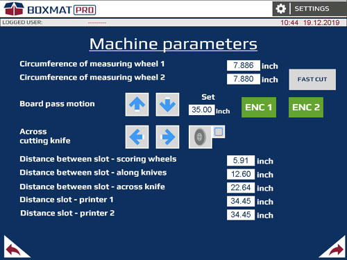
Fig. 32. The Machine Parameters’ screen (3/5)
78. Circumference of measuring wheel 1 and 2 - the exact circumference of the measuring wheels.
79. Board Pass Motion ![]() Press and hold to move the corrugated sheet in or out of the machine. Press
Press and hold to move the corrugated sheet in or out of the machine. Press ![]() for forward and
for forward and ![]() for reverse.
for reverse.
80. Set - the distance the board will travel after pressing the Encoder 1 or Encoder 2 buttons, measured by measuring wheel 1 or 2.
81. Encoder 1 - the button starts passage of the board for encoder 1.
The button should be enabled when the board is under encoder 1.
82. Encoder 2 - the button starts passage of the board for encoder 2.
The button should be enabled when the board is under encoder 2.
83. ![]() the buttons for the manual operation of the across knife:
the buttons for the manual operation of the across knife:
- moves the knife to the left;
- moves the knife to the right.
84. The graphic shows the across cutting knife. Pressing on the picture will lift or lower the knife. The lowering of the knife is indicated by a green "tick" ![]() .
.
85. Distance slot-along scores – the distance from the center of the scoring beam to the center of the scoring wheels.
86. Distance between slot - along knives – the distance from the center of the scoring beam to the rotary knife.
87. The distance between slot - across knife – the distance from the center of the scoring beam to the across knife.
88. Distance slot – printer 1 – the distance from the center of the scoring beam to the printer module 1.
89. Distance slot – printer 2 – the distance from the center of the scoring beam to the printer module 2.
90. ![]() - this button returns to the previous screen (Fig. 31).
- this button returns to the previous screen (Fig. 31).
91. ![]() - this button leads to the next screen (Fig. 33).
- this button leads to the next screen (Fig. 33).
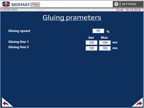
Fig. 33. The Machine Parameters’ screen (4/5) (option)
92. Gluing speed – Speed of the gluing head during glue mode (option).
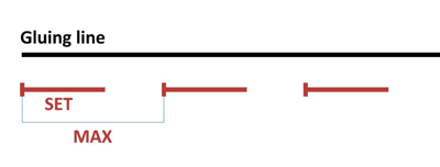
Fig.34. The setting of gluing line
93. Gluing line 1 – Set – Opening time of the gluing head for the gluing line 1 (Fig.34) (option).
94. Gluing line 1 – MAX – Cycle time of the gluing head for the gluing line 1 (Fig.34) (option).
95. Gluing line 2 – Set - Opening time of the gluing head for the gluing line 2 (Fig.34).
96. Gluing line 2 – MAX – Cycle time of the gluing head for the gluing line 2 (Fig.34) (option).
97. ![]() - this button returns to the previous screen (Fig. 32).
- this button returns to the previous screen (Fig. 32).
98. ![]() - this button leads to the next screen (Fig. 35).
- this button leads to the next screen (Fig. 35).
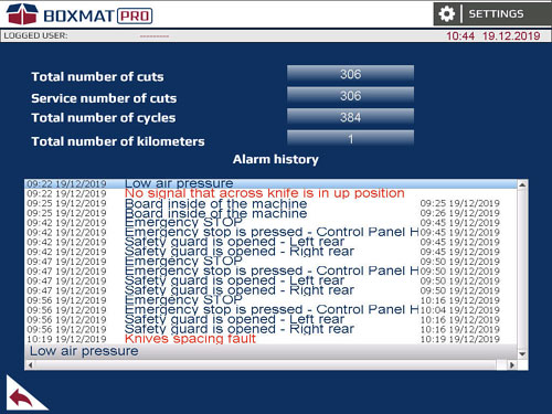
Fig. 35. The Machine Parameters’ screen (5/5)
99. Total number of cuts - the number of cuts made by the slotting beam since its inception.
100. Service number of cuts - the number of cuts made by the slotting beam since the last service.
101. Total number of cycles - the number of automatic work cycles since its inception.
102. Total number of kilometers - the number of kilometers of the boards measured by the encoders since its inception
103. Alarm history - the record of messages.
104. ![]() - this button returns to the previous screen (Fig. 33).
- this button returns to the previous screen (Fig. 33).
Service Screens
Service screens contain statistical information on the operation of the machine.
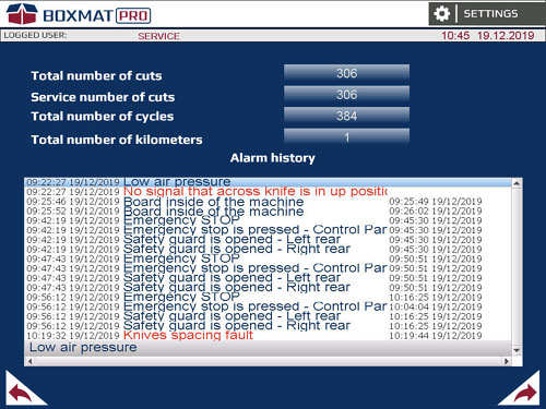
Fig. 36. Service Screen (1/3)
105. Total number of cuts - the number of cuts made by the slotting beam since its inception.
106. Service number of cuts - the number of cuts made by the slotting beam since the last service.
107. Total number of cycles - the number of automatic work cycles since its inception.
108. Total number of kilometers - the number of kilometers of the boards measured by the encoders since its inception
109. Alarm history - The record of emergency messages.
110. ![]() - this button returns to the previous screen (Fig. 24).
- this button returns to the previous screen (Fig. 24).
111. ![]() - this button leads to the next screen (Fig. 37).
- this button leads to the next screen (Fig. 37).
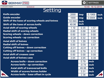
Fig. 37. Service screen (2/3)
For adjusting the ‘zero’ point for the tools and rolls
112. Knife encoder – sets the number of impulses per inch for the positioning of the slotting knives (i.e. 2000 = 0.1969”).
113. Left guide encoder – sets the number of impulses per inch for the left guide (i.e. 1000 = 0.0984”).
114. Shift of the base of the scores and knives – from the center of the machine to the “zero” position for scoring wheels and longitudinal knives.
115. Shift of the base of across knife – inactive
116. Axial shift of scores (3 sets) – the distance from the center of the scoring wheels to the point at which the gripper sensor detects it.
117. Radial shift of scores - correction for the rotary scoring point
118. Scoring wheels – down correction (3 sets) - offset for down action point on the board
119. Scoring wheels – up correction (3 sets) – offset for up action point on the board
120. Axial shift of knives (3 sets) - the distance from the center of the knives to the point at which the gripper sensor detects it.
121. Radial shift of knives (3 sets) - correction for the rotary blades cutting point
122. Cutting off knives - down correction (3 sets) – offset for down action point 0n the board
123. Cutting off knives - up correction (3 sets) – offset for up action point on the board
124. Axial shift of scores case (3 sets) – the distance from the edge of the case to the point at which the gripper sensor detects the tool
125. Axial shift of knives case (3 sets) - the distance from the edge of the case to the point at which the gripper sensor detects the tool
126. Across knife – down correction – offset for down action point on the board
127. Across knife – up correction – offset for up action point on the board
128. Axial shift of transversal knife – the distance from the center of the machine to the home position of across knife.
130. Across knife – base offset in cycle – offset for the first action point down on the board
131. ![]() - this button returns to the previous screen (Fig. 36).
- this button returns to the previous screen (Fig. 36).
132. ![]() - this button leads to the next screen (Fig. 38).
- this button leads to the next screen (Fig. 38).
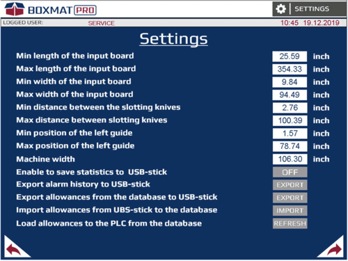
Fig. 38. Service screen (3/3)
133. JOG speed - slow pass of board - sets the speed of the boards in jog mode.
134. Pass speed – board exit - sets the speed of the boards when exiting the machine.
135. JOG speed - scoring beam - sets the speed of the scoring beam when controlled from the "Manual Movement" screen, by using the ‘Up’ and ‘Down’ arrows.
136. JOG speed - spacing of scores and knives - sets the speed of the scoring rolls and knives gripper when controlled from the "Manual Movements" screen.
137. Speed of the spacing scores and knives - sets the speed of the spacing of the scoring rolls and the knives after pressing the "Spacing - scoring and knives" button in the "Manual Movements" screen.
138. JOG speed - cut-off knife - sets the speed of the across knife when controlled from the "Manual Movements" screen.
139. Dry run (no board) - activation of the automatic cycle without a board.
140. Glue – enabling the glue mode allows the glue settings window to be unlocked
141. Printer qty - the number of print modules installed on the machine.
142. Number of knives - the machine can work using 4, 6 or 8 knives.
143. Number of scores - the machine can work using 4 or 6 scores.
144. Distance ENC1 – ENC2 – the distance from the measuring wheel 1 to the measuring wheel 2.
145. Reset service counter – enter the password and press the button RESET to clear service number of cuts.
146. ![]() - this button returns to the previous screen (Fig. 37).
- this button returns to the previous screen (Fig. 37).
147. System Menu – this button open system menu of touch panel
'FEFCO' Style Screens - Description on the Basis of RSC (Standard Style 201 REV)Following are the features available in the configuration screens for the RSC (FEFCO 0201 REV) standard style.

Fig. 39. Main the RSC style set-up screen
148. RSC - the FEFCO style selected.
149. ![]() - saves the current box into the machine's memory.
- saves the current box into the machine's memory.
150. QUANTITY SET - the number of boxes to be made.
151. QUANTITY DONE – the number of cartons already made. Next to it, there is a RESET button used to reset the count. To modify quantity done counter, use PLUS/MINUS buttons.
After completing the required number of cardboard boxes, the machine will stop. To continue production, the RESET button should be pressed, otherwise it will not be possible to start a new cycle
152. LENGTH - the internal length of the box required.
153. WIDTH - the internal width of the box required.
154. HEIGHT - the internal height of the box required.
155. THICKNESS - a field where the thickness of the cardboard from which the board is made, should be entered.
156. SCORING DEPTH MANUAL CORRECTION - beam scoring depth in %: The setting for the depth of the across score should be in range 0% to 100%
- value 0% - without scoring between the slots;
- value 100% - max scoring depth between the slots;
157. SCORING DEPTH MANUAL CORRECTION - + and - buttons for adjusting the depth of along scores on the board:
The setting for the depth of the scores should be selected according to preference.
158. SET THE LENGTH AND WIDTH OF PRESENT BOARD - this button opens a screen (Fig. 37) to add the input sheet size.
159. SETUP MACHINE – when all dimensions have been added also the sheet size this button moves all cutting/scoring tools to their correct positions.
160. MACHINE IS NOT SET – this indicates that not all information has been entered or machine is not setup. It will change to READY TO WORK when all is set.
161. START - starts the automatic box production in the current style.
162. STOP - stops the machine AFTER the whole board has passed through.
163. PRINT/GLUE (or PRINTING) – this button opens a screen to set parameters of printing (Fig. 40) (option).
164. ![]() - this button returns to the previous screen.
- this button returns to the previous screen.
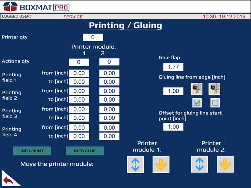
Fig. 40. Printing settings (option).
165. Printer qty - number of printers installed on the machine (option).
The machine can accommodate 1 or printers.
166. Action qty – a field with option of setting print fields on cardboard
The maximum number of prints is 4.
167. Printing field [1…4] - from – determines the position on the board where the printing head lift up (option).
168. Printing field [1…4] - to - determines the position on the board where the printing head move down (option).
169. Printer module 1 / 2 – checkboxes of the printer module (1 or 2) (option).
170. Move the printer module 1 (option):
- lift up/down the printer module
- or
 indicates the position of printer module
171. Move the printer module 2 (option):
- lift up/down the printer module
- orindicates the position of printer module
172. ![]() - this button returns to the previous screen.
- this button returns to the previous screen.
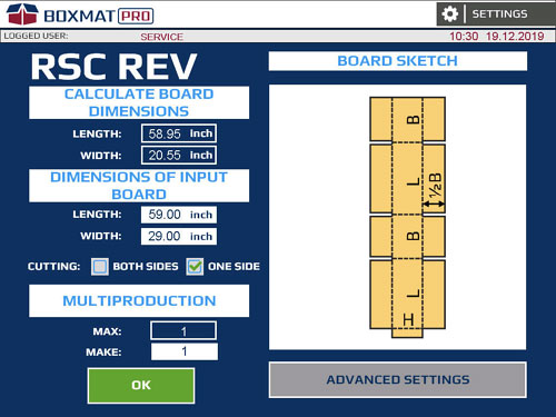
Fig. 41. The RSC style set-up screen – board dimensions.
173. Graphic showing the finished board in the selected FEFCO style.
174. LENGTH - the length of board required.
175. WIDTH - the width of board required.
176. LENGTH – enter the length of the input sheet.
177. WIDTH – enter the width of the input sheet.
178. CUTTING – cutting off scrap form:
- BOTH SIDES
- ONE SIDE
179. MAX – shows the number of current boxes that can be produced from the length of the current sheet.
180. MAKE - enter the number of boxes required from the sheet. The value may be lower or equal to the MAX value.
181. OK - accept all values entered into the screen and return to the previous screen (Fig. 39).
182. ADVANCED SETTINGS - the button opens a screen displaying the advanced settings for the current box (Fig. 42).
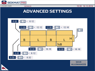
Fig. 42. RSC style setup screen - advanced settings
183. Blue field - current value of the carton panel length without allowances (Fig. 42 - 1)
184. White field - allowance value (Fig. 42 - 2)
185. Grey field - total value of carton panel length (Fig. 42 - 1) SAVE ALLOWANCES button - pressing the button saves the oversize into the oversize database. The changes made to the allowances will be restored to their previous values after exiting the style. In order to save the allowances permanently, press the SAVE ALLOWANCES button for about 1 second, the saved allowances will be confirmed by the message (Fig. 43).

Fig. 43. Confirmation window of saved allowances
The button is active after logging into the operator’s account.
Freestyle Screens

Fig. 44. The main, Freestyle configuration screen
186. Save the recipe - this button saves the currently configured parameters of the box to the machine's memory.
187. QUANTITY SET - a field where the specified number of boxes to be made in automatic mode can be entered; this is activated by pressing START
188. QUANTITY DONE - a field displaying the current number of cartons made in the automatic cycle. Next to it is a RESET button used to reset the count of the cardboard boxes made.
After completing the set number of cardboard boxes, the machine will stop. To continue production, the RESET button should be pressed, otherwise it will not be possible to start a new cycle.
189. LENGTH - a field where the length of the input board, from which the cardboard box is to be cut, can be entered.
190. WIDTH - a field where the width of the input board, from which the cardboard box is to be cut, can be entered.
191. THICKNESS – thickness of the input board, from which the cardboard box is to be cut.
192. MAX - a field in which the maximum possible number of boxes to be made, along its length - and in successive multi-production from one input board - is displayed.
193. MAKE - a field where the number of boxes can be entered which are to be made in multi-production from one input board along its length. This value may be lower or equal to the MAX value.
194. SCORING DEPTH MANUAL CORRECTION - beam scoring depth in [%].
The setting for the depth of the scores should be in range 0% to 100%:
- The value 0 % - without the scoring across.
- The value 100% - the deep scoring across.
195. SCORING DEPTH MANUAL CORRECTION - + and - buttons enable the depth of scores to be adjusted the longitudinal (along) the box:
- plus – a deeper score;
- minus – a shallower score.
The setting of the depth of the along and across scores should be selected experimentally depending on need.
196. ENTER ADDITIONAL DIMENSIONS - This button opens the box set-up screen in Freestyle - the first set-up screen (Fig.45).
197. SET UP MACHINE - the button shifts all available machine actuators to the set positions to make a carton.
198. MACHINE IS NOT SET / READY TO WORK - information about the actuators' position of the machine. READY TO WORK indicates that the machine is ready to make the box in the style selected.
199. START - the button starts the automatic cycle of box production in Freestyle.
200. STOP - the button stops the automatic production cycle of boxes, after the whole board has gone through the machine.
201. Return - a button to return to the previous screen - Others (Fig. 23).
202. COPY FROM FEFCO - the button copies the values of the settings of the recently used FEFCO style to Freestyle.
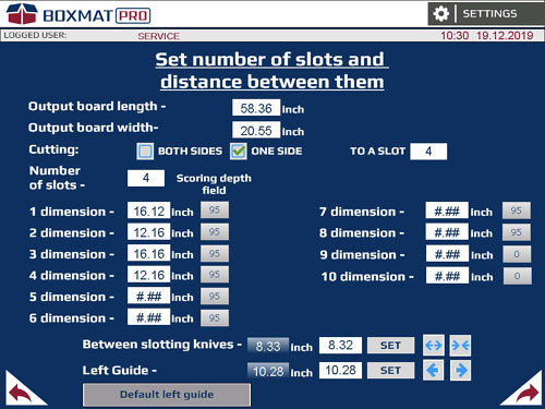
Fig.45. The Freestyle configuration screen - the first set-up screen
203. Output board length – length of the output board
204. Output board width - a field in which to enter the width of the output format.
205. CUTTING - formatting the input carton on one or both sides:
- BOTH SIDES - formatting of the input carton with two longitudinal knives. Double waste generation;
- ONE SIDE - formatting the input carton with a longitudinal knife. Single waste generation.
The CUTTING option is available if the following relationship is fulfilled: the input format is larger than the calculated format.
206. Cutting into the slot - formatting the input carton along the width with longitudinal knives from the beginning of the format to the selected transverse score. Entering the value 0 in the slot cutting field will format the format along its entire length.
207. Number of Slots - a field where the set number of cuts for the slotting knives to cut out the cardboard is determined.
208. Dimension 1 ... 10 - fields in which the distance between consecutive cuts with the slotting knives should be entered.
209. Scoring depth field – a choice of scoring depth of scoring beam (Fig. 46).

Fig. 46. OPTION window - depth of scoring beam.
210. Set box position - enter the distance at which the slotting knives should be spaced.
211. Set button - starts the slotting knives' movement to a position as entered in the Set box.
212. these buttons change the position of the slotting knives. Press and hold to move:
- the slotting knives move apart slowly
- the slotting knives move closer slowly.
The position of the slotting knives is measured as the distance from the front of the left knife to the front of the right knife. The knives slide down to the center of the machine evenly or move apart from the center of the machine. Spacing of the blades within the range 2¾“ to 78 ¾“ is possible.
When one of the buttons displays a yellow arrow, it indicates that the slotting knives have reached their destination.
213. Current Position - the field displays the current position of the board guide.
214. Set box - the field in which it is possible to enter the position at which the left board guide is to be set.
215. Set - this button moves the left board guide to the position in the ‘Set box’.
216. Board Guide ![]() Press and hold these buttons to change the position of the left, automatic, board guide.
Press and hold these buttons to change the position of the left, automatic, board guide.
The position of the left limiter is measured as the distance from the inner wall of the limiter to the center of the machine. It is possible to set the limiter within the range 1 ¾“ to 47”.
When one of the buttons displays a yellow arrow, it indicates that the left guide is in an extreme position and has reached its designated position.
217. Default left guide - restores the default position of the limiter.
218. Return - This button returns to the previous screen - Freestyle set-up screen - main (Fig. 44).
219. Forward - This button opens up the next screen - Freestyle set-up screen (Fig. 47).
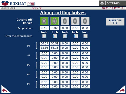
Fig. 47. Freestyle configuration screen- the second settings screen
220. Graphics showing longitudinal knives available. A graphics of the longitudinal knife highlighted in green indicates the active longitudinal tool used in the production cycle. The number of longitudinal knives available on the screen may vary depending on the selected cutting mode (from the right or from both sides) or no cutting.
The machine can handle 4, 6 or 8 knives. The maximum number of the supported knives depends on the additional options of the machine.
Fields display the set position of the cutting knife longitudinally relative to the left edge of the output format. In this field, it is possible to enter a position in which each knife is to be set.
The knives should be spaced in the same order as presented in the graphics, otherwise a message "Wrong data for the knives" shall be displayed.
221. Over the entry length – enabling the cutting option selected with a longitudinal knife along the entire length of the output format.
222. Longitudinal cutting P [1...5] - fields displaying cutting profiles for each longitudinal knife:
- Starting point P [1...5] - the value displayed in this field indicates the place on the format (or a fragment of the format intended for the box) in which the knife will be lowered measuring from the beginning of the format.
- End point P [1... 5] - the value displayed in this field means the place on the format (or piece of the format intended for the box) in which the knife will be lifted measuring from the beginning of the format.
223. Turn off all buttons - the button deactivates and resets all fields for active longitudinal knives.
224. Return - the button returns to the previous screen - Freestyle configuration screen - first settings screen (Fig. 47)
225. Forward - the button takes you to the next screen - Freestyle setup screen - the third Setup screen (Fig. 49).

Fig. 48. The freestyle configuration screen - the third Setup screen
226. Graphics shows the scoring wheels available. A graphics of the longitudinal score highlighted in green indicates the active longitudinal tool used in the production cycle.
The machine can handle up to 6 scoring wheels
227. Fields display the set position of the longitudinal score in relation to the left edge of the output format. In these fields, it is possible to enter a position foreach score in which it is to be set.
The rollers should be spaced in the same order as presented in the graphics, otherwise a message "Wrong data for the scores" shall be displayed.
228. Over the entire length - enables the scoring option with the selected longitudinal score along the entire length of the output format.
229. Longitudinal sing P [1... 5] - fields display scoring profiles for each longitudinally scoring wheel:
- Starting point P [1…5] - the value displayed in this field indicates the place on the format (or piece of format intended for the box) in which the scoring wheel will be lowered measuring from the beginning of the format.
- End point P [1... 5] - the value displayed in this field indicates the place on the format (or piece of the format intended for the box) in which the scoring wheel will be lifted measuring from the beginning from the format.
230. Turn off all button - deactivates and zeroes all fields for active longitudinal scores
231. Return - the button to return to the previous screen - Freestyle configuration screen - second settings screen (Fig.45).
232. Forward - the button to go forward to the next screen - Freestyle setup screen - the fourth Setup screen (Fig. 49).
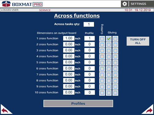
Fig. 49. The freestyle configuration screen – the fourth Setup screen
233. Across on output board – the number of transverse actions used on the carton.
234. 1…10 transverse movements - (where 1 – is the first transverse movement, 2 – is the second transverse movement, etc.) of the field where the distances between successive transverse movements should be entered.
The first transverse movement is measured as the distance of the blade from the beginning of the output format.
235. Profiles button – assigning the selected motion profile to a given transverse action. The range of motion for a given profile is available after pressing the Transverse Motion Profiles button.
236. Cutting and Gluing fields (option) - assigning an action for the lateral movement.
Only one action can be assigned to each lateral movement.
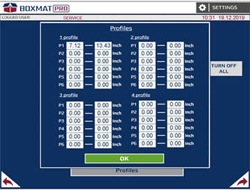
Fig. 50. Freestyle configuration screen - fourth settings screen - the Window of transverse motion profiles
237. Profile 1…4 – motion profiles for the transverse tool movement:
- Starting point P [1... 6] - place of lowering of the transverse tool,
- End point P [1... 6] - place of lifting of the transverse tool.
238. OK button - the button that closes the Transverse Movement Profiles window.
239. Return - the button to return to the previous screen - Freestyle configuration screen - third settings screen (Fig. 48).
240. Forward - the button to go forward to the next screen - Freestyle setup screen - the fifth setup screen (Fig. 51).
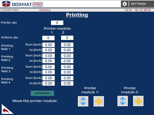
Fig. 51. Printing parameters screen (option)
241. Printer qty – the number of printed fields on the carton. A maximum of four printed fields on one carton are possible (optional).
242. Actions qty – the number of printed fields on the carton. A maximum of four printed fields on one carton are possible (optional).
243. Printing field [1…4] - form – sets the position in which printing begins on the format (optional).
244. Printing field [1…4] - to – sets the position in which printing ends on the format (optional).
245. Printing module selection fields (optional).
246. Raising the printing module 1 (optional):
- A blue up-down arrow - the button raises the printing module;
- A yellow arrow up-down – the button indicates in which position the printing module currently is.
247. Raising the printing module 2 (optional):
- A blue up-down arrow – the button raising the printing module;
- A yellow up-down arrow – the button indicating in which position the printing module currently is.
248. Return - the button to return to the previous screen - Freestyle configuration screen - fourth settings screen (Fig. 49) (optional).
Production of a Box in the Freestyle
Freestyle allows the User to independently set all the parameters related to board cutting.
The procedure for the FREESTYLE production of cardboard modeled after the RSC style:

Fig.52. BASIC CONSTRUCTIONS screen
1. In the main screen - BASIC CONSTRUCTIONS screen (Fig.52) select the OTHER button.
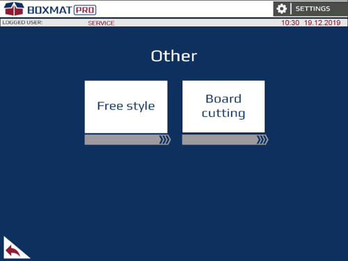
Fig.53. ‘Other’ Screen
2. In the ‘Other’ screen (Fig.53) select the Freestyle button.

Fig.54. The Freestyle configuration screen - main
3. In the main, Freestyle configuration window, the following parameters should be entered:
- Number of boards to be completed;
- Length, width and thickness of the input board;
- Across and Along scoring depth
4. Press ‘Enter additional dimensions’ - the first screen with settings for Freestyle will open.
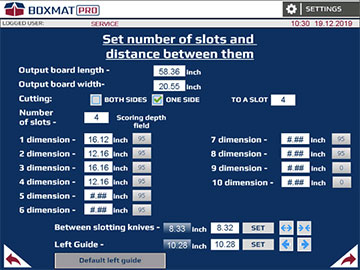
Fig.55. The Freestyle configuration screen - the first set-up screen
5. In the first Freestyle Settings screen, the following parameters should be indicated:
- Dimension (length and width) of the output format;
- Number of slots;
- Further dimensions between slots
- Depth of transverse score for individual slots;
6. In this window, the slotting knives should be appropriately spaced across the width and the left, automatic guide should be set to the desired position.
7. Press Forward – advance to the second Freestyle Settings screen ![]()

Fig. 53. The Freestyle configuration screen
8. In the second, Freestyle Settings screen, the following parameters should be indicated:
- activate the required number of longitudinal knives
- complete longitudinal cutting points
9. Press Forward – advance to the third Freestyle Settings screen ![]()
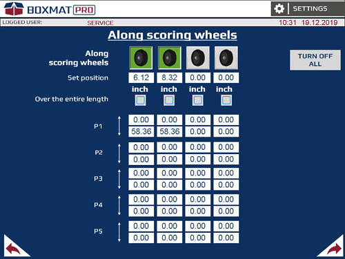
Fig. 54. The Freestyle configuration screen
10. In the third, Freestyle Settings screen, the following parameters should be indicated:
- activate the required number of longitudinal scores;
- complete longitudinal scoring points
11. Press Forward – advance to the fourth Freestyle Settings screen ![]()

Fig. 55. The Freestyle configuration screen
12. In the four Freestyle Setting screen, the following parameters should be indicated:
- Cross function the board
- Profiles for cross function;
- Checkboxes Cutting and Gluing (option) – an assigned action fo cross function
13. Press Forward – advance to the last Freestyle Settings screen ![]()

Fig. 56. The Printing settings screen (option)
14. In the Printing Settings screen, the following parameters should be indicated (option):
- number of printers
- number of actions for individual printers
- printing area - from [inch] and to [inch];
15. Go back to the main Freestyle configuration screen.
16. In the main Freestyle configuration screen, press the button "SET THE MACHINE" and wait until the message "MACHINE NOT SET" changes to "READY TO WORK".
17. Set the input buffers in the operating positions:
- spread the input rollers apart so that two of them are in positions on the ends of the board and the third is in the center,
- set the gap under the rollers to allow only one sheet of board to pass under.
18. Manually set the right guide to almost touch the board.
19. Place one board on the table and press the START button on the touch panel.
20. When the board has been cut, slotted and ejected, check that the length, width, slots and scores are as required. Adjust if necessary.
Production of Boxes in the RSC (FEFCO Style 0201)
The procedure for the production of boxes in the FEFCO style based on the RSC (0201)example.

Fig. 57. BASIC CONSTRUCTIONS screen
1. In the main - BASIC CONSTRUCTIONS screen(Fig.57) select the Slotted-type Boxes button.

Fig.58. The screen contains templates for the Flap Box styles FEFCO 2xx
2. In the first screen select button RSC (0201).
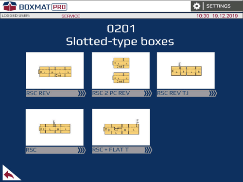
Fig. 59. The screen contains templates for the Box styles 0201
3. In the first RSC (0201 REV) screen select the RSC button.

Fig. 60. Main RSC style set-up screen
4. In the main configuration window of the RSC style, enter the following parameters:
- The number of boards to be completed;
- The internal dimensions of the box and the thickness of the cardboard;
-
The along and across depth of the scoring.
5. Press the button SET CURRENT LENGTH AND WIDTH OF THE BOARD - the first screen for the settings for the RSC style will open. Further screens make it possible to introduce offsets (see section 7.6).
6. Press the button PRINTING - the screen for the printing settings will open. Enter parameters of printing. (see section 7.6).
7. In the main Freestyle configuration screen, press the button "SET THE MACHINE" and wait until the message "MACHINE NOT SET" changes to "READY TO WORK".
8. Set the input buffers in the operating positions:
-
spread the buffers apart so that both of them are in positions on the ends of the board and the third is in the center part, above the roller.
-
set the gap under the buffer to allow insertion of one sheet of cardboard. At the same time, render insertion of two sheets of cardboard impossible.
9. Manually set the right guide to almost touch the board
10. Place one board on the table and press the START button on the touch panel.
11. When the board has been cut, slotted and ejected, check that the length, width, slots and scores are as required. Adjust if necessary.
Tool Replacement Procedure
The procedure for the tool replacement is as follows:
 ATTENTION: Works in the cutting, scoring or transporting zone can be performed by the trained staff only observing special caution. In these zones, there is an increased risk of injury to various parts of the body.
 All work carried out when operating the machine SHOULD always be done with suitable protective gloves on.
1. Open the rear covers of the machine.
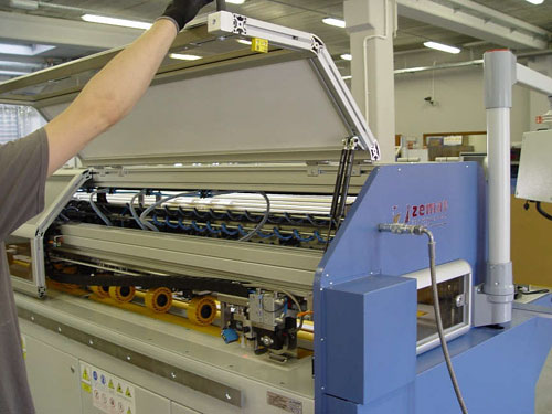
Fig. 56. Tool replacement procedure
2. Extend the assembly pivot. In case of a difficult access, slide out the no crush rollers.
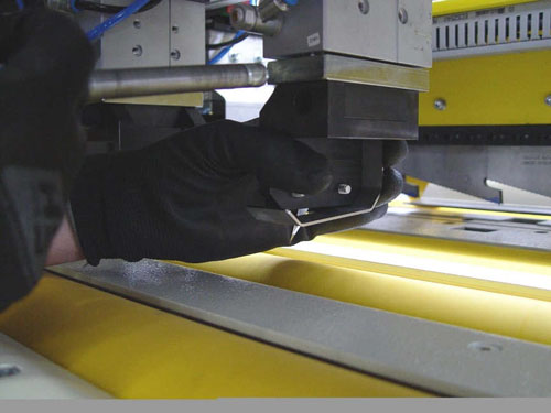
Fig. 57. Tool replacement procedure
3. Remove the tool holder.
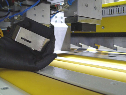
Fig. 58. Tool replacement procedure
![]() When changing razor blades, pay special attention to the blade - a mechanical impact can damage it.
When changing razor blades, pay special attention to the blade - a mechanical impact can damage it.
4. Replace the tool.
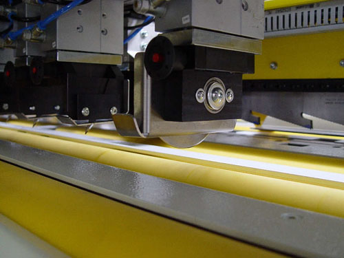
Fig. 59. Tool replacement procedure
5. Close the machine's rear covers.
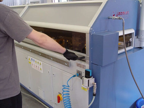
Fig. 60. Tool replacement procedure
6. Press the RESET button
7. On the machine parameters screen, select the type and orientation of the tool for which the changes were made on the machine.
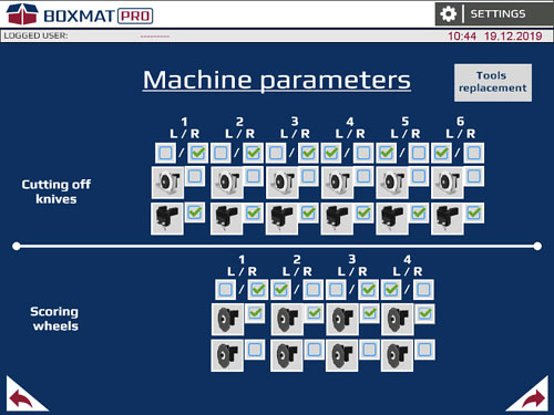
Fig. 61. Machine parameters screen
Board Cutting Mode
The board cutting procedure is presented below:

Fig. 62. "BASIC CONSTRUCTIONS" screen
1. In the main screen – the BASIC CONSTRUCTIONS screen - select the OTHERS button.
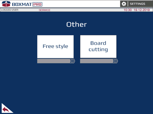
Fig. 63. "Others" screen
2. On the "Others" screen, choose the board cutting button.
3. In order to cut the form, enter the position value for the limiter and then press the SET button.
4. Set the input buffers to their operating positions:
- spread the buffers apart, so that both of them are in positions on the ends of the form and the third one is in the centre part above the roller,
- set the gap under the buffer to allow insertion of one cardboard sheet into it, while at the same time, rendering insertion of two cardboard sheets impossible.
5. Manually, set the right limiter to make it almost stick to the form, leaving a 0.04” clearance to prevent the forms from jamming between limiters.
6. Enter the positions of the cutting knives, corresponding to the widths of the output forms, into the fields marked CUTTING KNIVES / SET VALUES .
7. After entering the desired knife positions, press the SETUP (SPACING OF SCORES AND KNIVES) button.
Starting the procedure for setting up the grooves/scores and knives will signal a change to the back-light button, marked SCORES AND KNIVES.
8. After completing the spacing operation, lower the cutting knives responsible for form cutting, by pressing the icon of the given knife. The knife being lowered will be ticked green.
9. Enter the number of input forms.
10. Place one form on the table and press the START button on the touch panel.
11. The end of the cycle takes place after the set number of input forms has been completed or after pressing the STOP button.
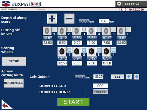
Fig. 64. Board cutting screen
Recipes - Description of the Recipe Window
In order to open the recipe window, proceed as follows:
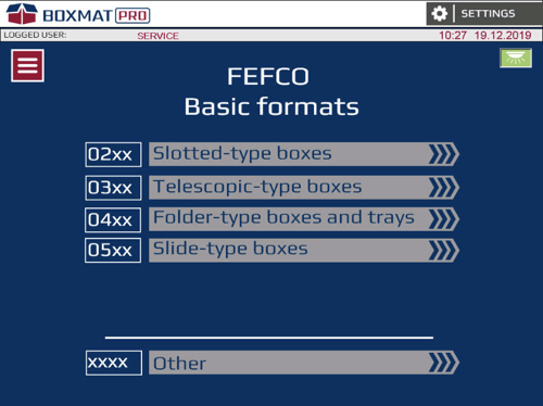
Fig. 65. "BASIC CONSTRUCTIONS" screen
1. In the main screen – the BASIC STRUCTURES screen - select the Login icon
2. In the Login screen, select the Recipes button.

Fig. 66. The screens for Login, Recipes and Production Statistics
3. In the Login, Formulas and Production Statistics screen, select the Recipes button.
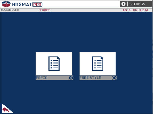
Fig. 67. The FEFCO recipes and the ANY STYLE/FREE STYLE selection screen.
4. In the Recipes screen, select one of the available groups of recipes, such as the FEFCO recipes.
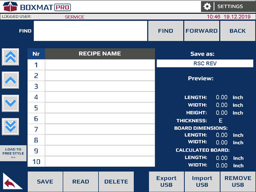
Fig. 68. FEFCO Recipes screen
5. The recipes screen is divided into two main areas:
- list of recipes and
- information about the style saved.
6. In the left part of the screen, there is a list of recipes with those recipes created by the User as well as buttons for saving, reading and deleting recipes. To the left of the list of recipes there are buttons for scrolling down the recipe list.
7. The right part of the screen displays basic information regarding:
- the internal dimensions of the saved box (length, width, height and thickness of the cardboard from which it was made) - Fields available in the FEFCO RECIPES.
- the dimensions of the input form (length, width).
- the dimension of the calculated form (length, width).
8. Description of the fields and buttons on the recipes screen:
- USB Export - Creating a copy of recipes on a portable memory, such as a pen-drive;
- USB Import - Restoring copies of recipes stored on a portable memory, such as a pen-drive;
- REMOVE USB - safe removal of a portable memory, such as a pen-drive;
- FIND - Searching by the recipe's name, as specified in the Search field;
- FORWARDS - Searching forwards in the recipe list for a recipe, with the name entered in the Search field;
- BACKWARDS - Searching backwards in the recipe list for a recipe, with the name entered in the Search field;
- SAVE - Allows the recipe in the recipe list to be saved;
- READ - Loading the recipe and automatically transferring it to the window of the FEFCO style or of the Free style;
- DELETE - Deletes the selected recipe from the list of recipes. In order to delete the selected recipe, hold the button down for 1 second.
- SAVE AS - The proper name for the style recipe created;
- LOAD TO FREE STYLE - Copy the FEFCO recipe to the free style (Option available on the FEFCO Recipe Screen);
- PREVIEW - Displays the type of recipe.
Recipes - Saving a Recipe - FEFCO Style
The recipe saving procedure in the FEFCO Style is as follows:
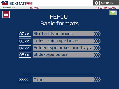
Fig. 69. "BASIC CONSTRUCTIONS" screen
1. In the main screen – the BASIC CONSTRUCTIONS screen – select, for example, 02xx Flap Boxes.
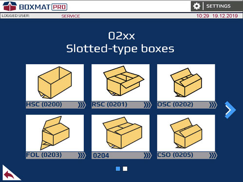
Fig. 70. Screen 02xx Flap Boxes
2. Then choose the style of the box, e.g. RSC (0201)

Fig. 71. 0201 style screen
3. Select the type of format for the box, e.g. RSC
4. After entering the internal dimensions of the box, press the "SET LENGTH AND CURRENT FORM" button, specifying the dimensions of the input form then, after confirming the same with the OK button, "SET THE MACHINE".
After the "READY TO WORK" message appears, use the button with a white arrow against a green background which is located at the top of the screen of a given FEFCO Style, in order to save the recipe to the machine's memory.
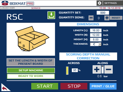
Fig. 72. FEFCO Recipes screen
5. After pressing the button, the recipe window for the FEFCO style will open automatically.

Fig. 73. FEFCO Recipes screen
6. Then enter the name of the recipe in "Save under the name" e.g. “RSC”
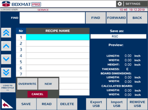
Fig. 74. FEFCO Style Recipes screen
7. To save the recipe under a given name, press the SAVE button and then choose one of the two available saving options. The OVERWRITE option replaces the recipe or another area marked on the list. The NEW option stores the recipe as a new item in the FEFCO recipe list.
The OVERWRITE option removes the overwritten recipe without the option of restoring it.
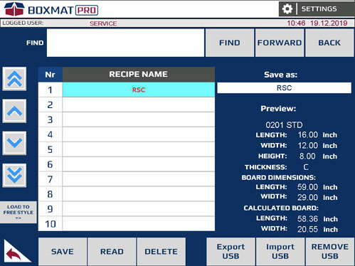
Fig. 75. FEFCO Style Recipes screen with a saved recipe
8. The figure shows a correctly saved recipe in the FEFCO Style.
Recipes - Saving Recipes - Free Style
The recipe saving procedure in the FREE Style is as follows:

Fig. 76 "BASIC CONSTRUCTIONS" screen
In the main screen – the BASIC CONSTRUCTIONS screen, select the OTHERS button.

Fig. 77. "OTHERS" screen.
1. In the Others screen, choose the FREE STYLE button.
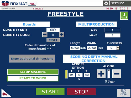
Fig. 78. View of the Free Style screen
2. Enter the position values for the tools used and "SET THE MACHINE"
3. Then press the button with the white arrow against a green background located in the upper right corner of the Free Style screen.
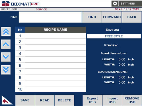
Fig. 79. Free Style recipes screen
4. After pressing the button, the recipe window for the Free Style will open automatically.
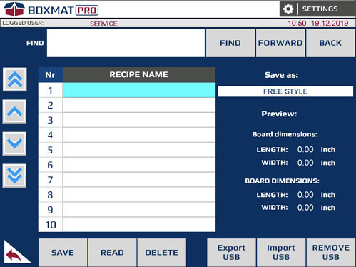
Fig. 80. Free Style recipes screen.
5. Then enter the name of the recipe in the "Save under the name".
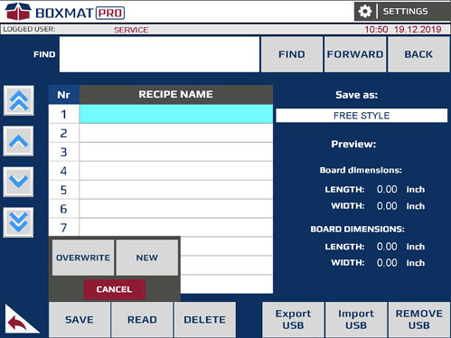
6. To save the recipe under a given name, press the SAVE button and then choose one of the two available saving options. The OVERWRITE option replaces the recipe, or another area marked on the list. The NEW option saves the recipe as a new item in the list of Free Style recipes.
The OVERWRITE option removes the overwritten recipe without the option of restoring it.

Fig. 82. The Free Style recipes screen with a saved recipe
8. Presents a correctly written recipe in the Free Style.
Recipes - Reading Recipes
The following is the procedure for loading a recipe:

Fig. 83. "BASIC CONSTRUCTIONS" screen
1. In the main screen – the BASIC CONSTRUCTIONS - screen select the MENU button.

Fig. 84. The screens for Login, Recipes and Production Statistics
2. In the Login, Formulas and Production Statistics screen, select the Recipes button.
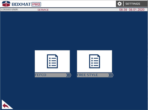
Fig. 85. The FEFCO recipes selection screen and the FREE STYLE selection screen
3. To read the recipe from the FEFCO Style or Free Style, select the appropriate icon.
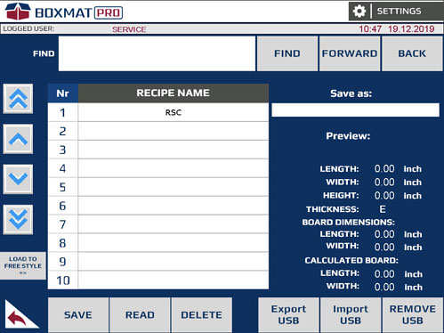
Fig. 86. FEFCO recipes screen.
4. Select the recipe to be loaded. The selected recipe will be highlighted in blue.
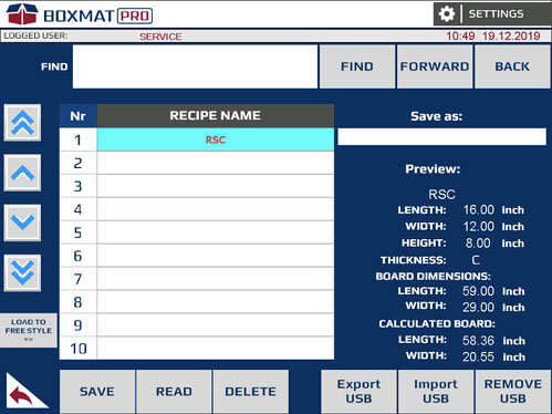
Fig. 87. FEFCO Recipes screen
5. Then press the READ button.
6. After loading the recipe, the system transfers the User to the currently loaded style from the FEFCO recipes. However, reading formulas from the Free Style recipe, takes the User to the Free Style screen.
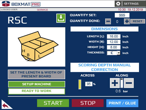
Fig. 88. The RSC screen
Alarms, Error Messages, and Failures
If the machine does not operate when required, it is likely that something has been overlooked. In this case, error messages will be displayed on the HMI panel.
EMERGENCY STOP – the machine was stopped by activation of the EMERGENCY STOP button or one of the limit switches at the protective covers, to eliminate the reason for this alarm, check if all the machine covers and casings are properly closed or turn the mushroom emergency stop switch clockwise (it will get unlocked). Then press the green RESET button.
LOW AIR PRESSURE - no or too low air pressure in the pneumatic system. It should be made sure that the machine is connected to the compressed air system at a suitable pressure level, and then an appropriate pressure in the machine should be set by turning the reduction valve of the compressed air preparation system.
TOO LOW AIR PRESSURE FOR SCORING WHEELS - too low or too high air pressure for longitudinal scores. The alarm is deleted with the RESET button.
ERROR SERVO DRIVE - BOARD – signals the occurrence of an alarm on the servo drive of the travel motor. The alarm is deleted with the RESET button.
ERROR SERVO DRIVE - LEFT SCORING BEAM - signals the occurrence of an alarm on the left servo drive of the scoring beam motor. The alarm is deleted with the RESET button.
ERROR SERVO DRIVE - RIGHT SCORING BEAM - signals the occurrence of an alarm on the right servo motor of the scoring beam. The alarm is deleted with the RESET button.
ERROR SERVO DRIVE - SCORING WHEELS AND KNIVES – signals the occurrence of an alarm on the servo drive of knives and scores. The alarm is deleted with the RESET button.
ERROR SERVO DRIVE - ACROSS KNIFE - signals a problem with the servo drive of the transverse knife motor. The alarm is deleted with the RESET button.
SCORING WHEELS SPACING FAULT – signals a problem with the precise positioning of the scoring rollers at the positions set. The alarm is deleted with the RESET button on the HMI touch panel.
KNIVES SPACING FAULT - signals a problem with the precise positioning of the longitudinal knives at the positions set. The alarm is deleted with the RESET button on the HMI touch panel.
ERROR DURING REFERENCING OR SPACING THE ALONG TOOL GRIPPER – signals a problem with homing or positioning of the longitudinal tool carriage. The alarm is deleted with the RESET button.
ERROR DURING REFERENCING OR POSITIONING THE ACROSS – indicates a problem with homing or positioning of the transverse tool. The alarm is deleted with the RESET button.
ERROR DURING REFERENCING OR POSITIONING THE SCORING BEAM - signals a problem with homing or positioning of the scoring beam. The alarm is deleted with the RESET button.
LEFT GUIDE SETUP FAULT – signals a problem with the precise positioning of the limiter in the set position. The alarm is deleted with the RESET button.
SLOTTING KNIVES SETUP FAULT - signals a problem with the precise positioning of the slotting knives in the set position. The alarm is deleted with the RESET button.
SLOTTING KNIVES ERROR - END POSITION REACHED – signals that the machine has reached the minimum position for the slotting knives during its setting. The alarm is deleted with the RESET button.
SLOTTING KNIVES ERROR - SCORING BEAM NOT REFERENCED – setting of the slotting knives is possible after the scoring beam has been homed. The alarm is deleted with the RESET button
MACHINE SETTING FAULT – signals a wrong setting of the machine for the production cycle. The alarm is deleted with the RESET button
NOT ENOUGH OF SCORING ROLLS – signals that the number of longitudinal scoring type is insufficient for a given box.
NOT ENOUGH OF ALONG CUTTING KNIVES - signals that the number of longitudinal knives is insufficient for making a given box.
NOT POSSIBLE TO SET UP SCORING ROLL [1…8] – the dimensions of the box introduced prevent the spacing of scores in a given position due to the required minimum distance between the tools. If this message occurs, change the orientation of the tools or increase dimensions of the box. The minimum distance between the tools is included in the attachment. The alarm is deleted with the RESET button.
SET POSITION OUTSIDE WORKING AREA – SCORING WHEEL [1…8] – signals the setting of the longitudinal score in an inaccessible zone. The alarm is deleted with the RESET button
NOT POSSIBLE TO SET UP ALONG KNIFE [1…8] – dimensions of the box entered prevent the spacing of knives in a given position due to the required minimum distance between the tools. If this message occurs, change the orientation of the tools or increase dimensions of the box. The minimum distance between the tools is shown in the attachment. The alarm is deleted with the RESET button.
SET POSITION OUTSIDE WORKING AREA - ALONG KNIFE [1…8] – signals the setting of the longitudinal knife in an inaccessible zone. The alarm is deleted with the RESET button.
CAN'T SETUP SCORING WHEELS – signals an attempt to set the longitudinal score in an inaccessible area. The alarm is deleted with the RESET button.
CAN'T SETUP ALONG CUTTING KNIVES – signals an attempt to set the longitudinal knife in an inaccessible area. The alarm is deleted with the RESET button.
WRONG DATA FOR THE ACTIONS OF SCORING WHEELS – signals when the longitudinal action is too short for the longitudinal score. The alarm is deleted with the RESET button.
WRONG DATA FOR THE ACTIONS OF ALONG KNIVES – signals a too short longitudinal action for the longitudinal knife. The alarm is deleted with the RESET button.
WRONG DATA FOR THE ACTIONS OF ACROSS TOOL - signals a too short transverse action for the transverse tool. The alarm is deleted with the RESET button.
NO SIGNAL THAT ACROSS KNIFE IS IN DOWN POSITION or NO SIGNAL THAT ACROSS KNIFE IS IN UP POSITION – signals an incorrect position of the transverse knife. In order to eliminate the cause, check air supply to the actuator, operation of the inductive sensor located on the actuator and mechanical operation of the actuator without air supply to the actuator. The alarm is deleted with the RESET button.
SCORING WHEELS AND KNIVES SEARCH FAULT – an alarm occurs during the search procedure for scores and knives. Check the drive system responsible for the spacing of scores and knives. The alarm is deleted with the RESET button.
WRONG NUMBER OF BOARDS TO MAKE – signals an input format that is too short in relation to the calculated format.
INPUT BOARD TOO SHORT – signals an input format that is too short in relation to the calculated format. The alarm is deleted with the RESET button.
INPUT BOARD TOO NARROW - signals an input format that is too narrow in relation to the calculated format. The alarm is deleted with the RESET button.
INPUT BOARD TOO LONG – signals that the length of the input format is more than 354”. The alarm is deleted with of the RESET button.
INPUT BOARD TOO WIDE – signals that the width of the input format is more than 94”. The alarm is deleted with the RESET button.
THERE IS PROBLEM WITH CARDBOARD MOVEMENT – signals the occurrence of an alarm when the format slips in the machine. The alarm is deleted with the RESET button.
BOARD INSIDE OF THE MACHINE – the message appears after pressing the START button or the HOME button (the guillotine homing button in the SETTINGS window) when there is a cardboard box or other object under the input or output laser sensor activating it. The alarm is deleted with the RESET button.
EMERGENCY STOP IS PRESSED - CONTROL PANEL HMI or EMERGENCY STOP IS PRESSED - REAR or EMERGENCY STOP IS PRESSED - RIGHT SIDE – the messages indicate that one of the safety switches on the machine has been pressed. The alarm is deleted with the RESET button.
SAFETY GUARD IS OPENED - LEFT FRONT or RIGHT FRONT or LEFT REAR or RIGHT REAR or LEFT REAR AT THE BOTTOM OR LEFT REAR AT THE BOTTOM – a message indicates the opening of covers on the machine. To reset the alarm, close the covers and press the RESET button.
WINDOW IS OPENED - LEFT or WINDOW IS OPENED - RIGHT –the opening of a window located on the side wall of the machine. To reset the alarm, close the open window and press the RESET button
REAR LEFT SAFETY GUARD NOT BLOCKED or REAR RIGHT SAFETY GUARD NOT BLOCKED – signals that the lock is not closed. To reset the alarm, press the RESET button.
8.0 Maintenance
General Notes
The machine operators can easily conduct most basic maintenance duties and preventative inspections as the machine is designed and built to operate with minimum maintenance to reduce stoppage periods.
However, some of the above mentioned operations are strongly recommended to be performed by the Manufacturer's qualified and experienced service technicians (it applies mainly to machine failures).
Complex maintenance and repair activities should not be performed without obtaining prior permission from the owner or manufacturer.
It is recommended to provide a Machine Repair Log where dates and types of repairs as well as preventative maintenance activities will be recorded.
Under no circumstances should anyone reach into the machine without taking all precautions to eliminate risk by shutting of all electrical and air supplies.
Particularly during maintenance operations or any other manual operations that may be required during preventive inspections, do not place any body parts in real and foreseeable danger zones before eliminating potential and foreseeable emergency situations.
 ATTENTION: Work performed in the zones of feeding, cutting or scoring systems should be conducted only by qualified personnel and only after taking all precautionary measures. In the above mentioned zones the highest level of potential body injuries is possible.
All machine's operators performing maintenance or preventive activities must always wear protective clothing and ant-slip boots to limit the risk of slipping/falling.
Before performing any work at the machine, always check that cuffs are properly buttoned, zipped around the wrists or neatly tucked up. Personnel should always remember to protect their hair against being pulled into the machine by rollers and belts.
All maintenance or repair activities should be conducted only by qualified personnel who are trained to interpret machine failures, can read diagrams of installed systems and engineering drawings in such a way that all possible disassembly or assembly procedures connected with standard maintenance operations are performed professionally and, most of all, safely.
![]() ATTENTION: Switchbox inspection and electrical systems maintenance can be performed only by certified electricians with valid training.
ATTENTION: Switchbox inspection and electrical systems maintenance can be performed only by certified electricians with valid training.
![]() ATTENTION: Under no circumstances should any of the maintenance, repair or preventative activities be conducted when the machine is operating or is connected to a power supply unit.
ATTENTION: Under no circumstances should any of the maintenance, repair or preventative activities be conducted when the machine is operating or is connected to a power supply unit.
Preventative Program, Periodical Inspection
AT THE BEGINNING OF EACH WORKING SHIFT CHECK IF:
- working space is clean, clear and safe;
- check the amount of solid impurities, leaks, and dust settling in/on the machine and all its components, if necessary clean it with a vacuum cleaner or a compressed air gun;
- clean the bottom knives in the counter-top;
- visually check the closing of all protective covers;
- sufficient level of lightning is provided to the working space;
- check the effectiveness of safety switches (EMERGENCY STOP), limit switches protecting movable covers and safety locks;
- Check AFTER 100 WORKING HOURS of the machine – or weekly:
- correct attachment and tightening of the load-bearing screws; check the tension of transport drive belt;
- clean the filter in the air preparation assembly
- Check AFTER 1,000 WORKING HOURS of the machine – or every 3 months:
- check effectiveness of the electric shock protection
- visually check the condition of mechanical components
- tighten all screw connections
- check the condition of the basic contact elements (contactors, relays), replace elements with worn connection surfaces.
9.0 Occupational and Safety Rules
The built-in safety features within the machine are designed to minimize any failures and to ensure that the safety requirements are met to minimize the risk of injury by maintaining a high level of safety.
The machine has many integrated safety features for the protection of operators and other personnel including:
- time-delay fire protection;
- limit switches to detect open/insecure covers and guards;
- safety lock with a latch
- decay phase sensor;
- covers and guards to protect from movable parts of the machine;
- easily accessible EMERGENCY STOP button installed on the main control panel;
- additional protection systems implemented in machine's control algorithm in order to halt the machine in potentially dangerous situations;
- the machine construction designed to provide the maximum level of safety for its operators.
Basic Safety Rules
Issues connected with safety rules and the evaluation of potential risk deriving from human-machine contact have been thoroughly covered in previous chapters of this service manual in which similar situations were presented. However, the importance of personnel safety is so profound that the Manufacturer has repeated the information once more here.
- All BOXMAT PRO operators must be acquainted with general safety rules implemented in the industrial workplace.
- In order to perform the optimal and safe machine use, this service manual should be read thoroughly and the user is strictly advised to follow all the instructions with a special focus on safety and warning signs.
- The final legal and financial responsibilities for all and any potential events derived from either the ignorance of the text of this service manual or the safety and occupational rules lies upon the purchaser. It is COMPLETELY AND ABSOLUTELY OBLIGATORY to read and follow these instructions.
- On the basis of the text included in this service manual and the knowledge derived from the manufacturer’s own product technology experience, the purchaser is strictly obliged to work out their own WORK STATION INSTRUCTIONS for their own machine operators.
- Each operator should read the text of this service manual before performing any work at the machine and should read any WORK STATION INSTRUCTION.
- Under no circumstances should the machine be operated by untrained personnel. The machine operators must be familiar with the occupational health and safety rules, and with a special focus on the risk created by the machine.
- Periodical preventative inspection of the fire protection system must be performed in the operated machine. The purchaser is fully responsible for making arrangements for conducting such inspection
- According to the manufacturer’s recommendations, the machine should be installed in the industrial environment only.
- Life threatening level of high power network voltage of 3 x 480 VAC, 50/60 Hz is delivered to the machine. As a result, all service or preventative activities should be performed only by well-trained personnel with qualifications required by law.
- UNDER NO CIRCUMSTANCES should any measures leading to decrease the machine safety status (such as blocking master switches or removing shields etc.) be undertaken by the purchaser or operator
- Any maintenance or other activities performed when the machine is running or when at a lowered standard of machine protection (while the shields are open or when the safety switches are defeated) must be kept to an absolute minimum before the full status of safety is restored.
- UNDER NO CIRCUMSTANCES should the machine be assembled, disassembled or transported by unqualified personnel or those unfamiliar with the safety rules included in this service manual as the said activities may lead to an accident or may become the cause of financial losses.
- The machine’s initial start-up should be conducted in the presence and under the supervision of Contractor’s agents.
- The machine’s test procedure, implemented always before the Buyer is entering the phase of full use of the machine, shall be performed only by an authorized person.
- Any change of any part, or use, of the machine which is inconsistent with that described in this service manual may lead to machine failures or become the cause of an accident.
- The machine's work parameters were pre-set by the Manufacturer in the most optimal way due to the installed rollers, cutting or scoring tools and electronic control systems. Any change in the machine's working parameters without the Manufacture's knowledge and permission may lead to an accident or poor performance.
Safety Conditions for the Personnel Directly Operating the Machine
![]() ATTENTION: To prevent serious injury, it is essential that all covers and guards are kept in place to protect personnel from the dangers present from moving shafts, blades, knives, etc. while operating this box-making machine.
ATTENTION: To prevent serious injury, it is essential that all covers and guards are kept in place to protect personnel from the dangers present from moving shafts, blades, knives, etc. while operating this box-making machine.
- It is advised that all and any personnel working with this or any other machinery should be trained and equipped to offer first aid assistance to any persons in the event of falls or accidents.
- The area surrounding this or any machine should not be blocked by any obstacles or waste product during its regular work cycle as this may cause stumbles, slips, falls or other accidents.
- The EMERGENCY STOP button is designed to be pressed at any time especially when an emergency shut-down is promptly needed.
- UNDER NO CIRCUMSTANCES should any moving parts of the machine be touched when working.
- UNDER NO CIRCUMSTANCES should any water based fire extinguisher equipment be used on or near the machine. Use only licensed non-water based firefighting agents and fire hazard protection products.
- UNDER NO CIRCUMSTANCES should any guards or covers be removed during machine work cycle.
- UNDER NO CIRCUMSTANCES should the operators stand or climb on the guards or covers.
- UNDER NO CIRCUMSTANCES should the operators stand or climb on the guards or covers.
- UNDER NO CIRCUMSTANCES should any oil, solvent or other caustic or toxic substances be allowed to come into contact with the machine.
- UNDER NO CIRCUMSTANCES should mobile phones be used near the machine direct environment.
- UNDER NO CIRCUMSTANCES should naked flames be used in the machine direct environment.
- UNDER NO CIRCUMSTANCES should cigarettes be smoked in the machine direct environment.
- UNDER NO CIRCUMSTANCES should alcohol be consumed in the machine direct environment nor should personnel under the influence of alcohol operate the machine.
- UNDER NO CIRCUMSTANCES should personnel consume meals in the machine direct environment.
- IT IS ESSENTIAL to use ALL covers and guards designed for the machine.
- IT IS ESSENTIAL that any accidents or machine failures should be promptly reported to the management.
- IT IS ESSENTIAL to use suitable working clothing to limit the possibility of being snagged or dragged into the machine.
- IT IS ESSENTIAL to wear protective gloves while operating the machine.
- IT IS ESSENTIAL to wear anti-slip, safety footwear.
- IT IS ESSENTIAL to use hair covering to minimise the possibility of being snagged or pulled into the machine.
- IT IS ESSENTIAL to keep the floor around the machine clean and clear of all debris and waste material.
- IT IS ESSENTIAL to use hearing protection.
- IT IS RECOMMENDED to use the EMERGENCY STOP button whenever there is a situation where the machine or the operator are at risk.
- Careless handling of the machine during transport and/or relocation may lead to severe injuries or accidents.
- Only suitably trained personnel taking special precautionary measures can perform certain tasks inside the machine. In these areas there is increased risk of severe injuries.
- At no time should operators climb on the machine.
- The switchbox doors should always be closed even if the machine is not in operation.
- The machine operators are strongly advised to work only in the safe work zone which is outlined in the drawing below:
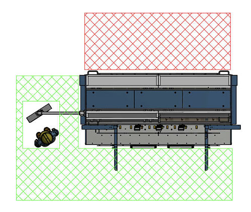
Fig.89. Tolerable boundaries of work zone during work cycle performed by Boxmat PRO. The area in which the machine's operators are not allowed to stay and perform their tasks at the machine was marked with the use of red color -the clearance zone around the machine should be no less than 59”.
Workplace Safety Rules During Maintenance, Repair, and Preventative Activities
- UNDER NO CIRCUMSTANCES should any service, maintenance or preventative measures be undertaken without full disconnection from supply network
- UNDER NO CIRCUMSTANCES should the machine be lubricated, cleaned or maintained while it is in operation.
- Switchbox and electrical systems maintenance can be performed only by suitably trained and qualified electrical engineers.
- Under no circumstances should the machine maintenance be conducted by unqualified or inexperienced engineers who are unfamiliar with the machine electrical wiring.
- Personnel performing maintenance activities should wear suitable protective clothing.
- Under no circumstances should the electrical system be modified in any way.
- The doors of the control system cabinet should be always locked and only authorized personnel should have access to the key.
Summary
Suitable measures should be taken during machine operation, its transport and installation procedures, and the repair, maintenance and preventative routines, to prevent the following situations:
- The machine should not be used in any way other than described herein;
- The machine should not be connected electrically with disregard to the provisions included herein;
- The machine should not be used inappropriately or used by untrained personnel;
- The machine should not be used with unsuitable materials;
- There must be sufficient suitable maintenance;
- There must be no unauthorized changes or alterations by unqualified or untrained personnel;
- There must be no use of non-original spare parts;
- There must be no personnel activities breaching the law and/or the regulations applicable to the workplace, as well as the provisions included in this service manual.
10.0 Electrical Documentation
10.1 POWER SUPPLY PARAMETERS – TECHNICAL DATASupply voltage 3 x 480 VAC; 50/60 Hz
Control voltage 24 VDC
Maximum power consumption 5.5 kW
10.2 LIST OF ELECTRICAL APPARATUSSee enclosure.
10.3 WIRING DIAGRAMSee enclosure.
11.0 Pneumatic Documentation
11.1. TECHNICAL DATA
Working pressure 0.6 – 0.8 MPa
Filtration accuracy 20 μм
Required class of working medium activity
4-4-4 according to ISO8573-1 standards
11.2 PRINCIPLE OF OPERATION
The working medium which is introduced to the system with the help of pressure reducing valve is subject to the initial filtration and then the reduction procedure due to which it is reduced to the required level. Then with the help of distribution valve controlled by the electro-pneumatic system the medium is delivered to the adequate servo-motor and as a result the said servo-motor is put in motion. Finally, the servo-motor motion will cause the relocation of razor blade due to which the glue flap will be cut off.
![]() ATTENTION: The purchaser is strongly advised to maintain the adequate 4-4-4 class of air cleanliness according to ISO8573-1 requirements even though the Manufacturer equipped the machine in the compressed-air preparation system.
ATTENTION: The purchaser is strongly advised to maintain the adequate 4-4-4 class of air cleanliness according to ISO8573-1 requirements even though the Manufacturer equipped the machine in the compressed-air preparation system.
The above mentioned pneumatic system does not require an extreme amount of attention, though, the user is obliged to control the level of condensation water in compressed-air filter tank periodically. If the presence of water is found, it should be emptied. If the significant amount of solid impurities in the tank are found, the tank must be dismantled, and then cleaned out with suitable cleaners. After cleaning out it should be aired with compressed-air and refitted. The detailed description of compressed-air system can be found in part titled CONTROLS AND INDICATORS AVAILABLE for OPERATOR.
11.4. PNEUMATIC SYSTEM DIAGRAM
See enclosure.
12.0 Utilization and Machine-Breaking
12.1 GENERAL NOTESIntroduced changes in law provisions or in process standards, which could not have been foreseen earlier, may become the cause of utilization and machine- breaking. This issue applies also to the machine's replaced or repaired parts and systems. In consequence, the purchaser is solely responsible for conducting the above mentioned procedures according to the binding provisions of law. It should be noted, however, that all machine's parts can be fully recycled.
12.2 WASTE MATERIAL
Hazardous waste should be always utilized by the companies which specialize in dealing with this kind of issue on a regular basis. The detailed list of type of waste produced by the machine in its life span is attached below:
- cardboard, corrugated board and other waste products;
- worn-out spare parts, which are divided into types of material from which they are made.
- All waste material deriving from machine parts' replacement or servicing even partially contaminated by grease cannot be discarded along with the industrial waste products.
![]() ATTENTION: It is strictly forbidden to place hazardous waste directly into the waste containers or use the municipal waste collectors to dispose of it.
ATTENTION: It is strictly forbidden to place hazardous waste directly into the waste containers or use the municipal waste collectors to dispose of it.
12.3 PHASES OF DISMANTLING PROCEDURE IMPLEMENTED for MACHINE-BREAKING
- Use MASTER SWITCH to switch off the machine;
- Machine must be placed in stable position on the floor.;
- Disconnect the machine from both pneumatic and electric power sources;
- Detach from the machine and disassemble both work tables (if they were ordered);
- Disconnect the flexible connections made of plastic and rubber, then utilize them with the help of companies which specialize in dealing with this kind of waste;
- Disconnect wiring systems and electrical equipment and then utilize them with the help of companies which specialize in dealing with this kind of waste.
- Divide metal waste into steel and non-ferrous and then break them up for scrap with the help of companies which specialize in dealing with this kind of waste.
13.0 Enclosures
Rating Plate