This instruction manual is intended to be a guide when operating the PS150. To ensure optimal performance from your welder, please follow the recommendations and specifications precisely.
Table of Contents
- Chapter 1: Intended Use
- Chapter 2: Explanation of Warnings
- Chapter 3: Electrical and Air Requirements
- Chapter 4: Principles of Heat Sealing
- Chapter 5: Principles of Operation
- Chapter 6: Machine Specifications
- Chapter 7: Component Replacement and Maintenance
- Chapter 8: Additional Machine Documents
For more technical information regarding this machine call our Resolution Center at 1-855-888-WELD or email service@weldmaster.com.
1.0 Intended Use
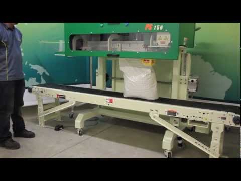
The PS150 is a rotary hot air welding machine intended to heat-seal weldable thermal plastics such as:
Polypropylene (PP) Coated Fabric
Polyethylene (PE) Coated Fabrics
The manufacturer does not approve of:
Any other uses for these machines.
The removal of any safety guards while in operation.
Unauthorized modification of the machines.
Using replacement parts that are not manufacturer-approved.
![]() Only a properly-trained technician may operate and/or perform any routine maintenance or repairs to the machines.
Only a properly-trained technician may operate and/or perform any routine maintenance or repairs to the machines.
NOTE: The manufacturer will not be held liable for any damage or injuries occurring from any inappropriate use of this machine.
2.0 Explanation of Warnings
There are several different warning symbols placed on the Miller Weldmaster PS150. The symbols are to alert the operator of potentially hazardous areas on the machine. Familiarize yourself with their placement and meaning.

Caution: Hot
The “Caution: Hot” symbol is placed on a guard near hot surfaces.

Danger: Pinch Points
The “Danger: Pinch Points” symbol is placed near any potential pinch points. Do not place any body parts near these sections of the machine while the machine is running.
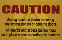
Caution: Unplug Machine
The “Caution: Unplug Machine” sticker is placed near the opening of the cabinet and all access panels. To prevent electrocution, the machine should always have the power disconnected before the cabinet door is open.

Warning: Keep Hands Clear
The“Warning: Keep Hands Clear” sticker is placed on the Heater Assembly. To prevent any pinching or burns, be aware of the location of your hands at all times.

Warning: High Temperature Air
The “Warning: High Temperature Air” sticker is placed on the Heater Assembly.

Caution: Electricity
The “Caution: Electricity” sticker is placed near areas that contain electrical.

Caution: Sharp
The “Caution: Sharp” sticker is placed near areas that contain sharp components.
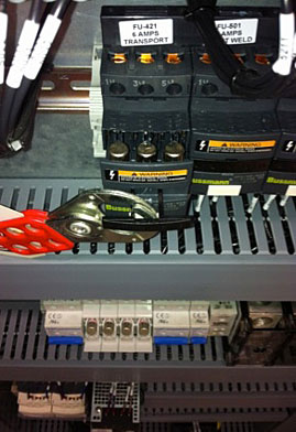
Lockout Tagout:
Each AC variable frequency drive power is supplied by a fuse block which can be locked out and tagged out. A screw driver is used in the slot on the face of the handle to start the handle to open. Once started then the user can pull open by hand and lockout tagout the device.
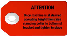
The Attention:
The tag is located near the lower limit of the height adjustment system. Once the machine has been adjusted to the desired operating height then raise the clamping collar to bottom of bracket and tighten in place. By doing so creates a lower height adjustment limit so that the machine will lower a minimal amount from operation height.
3.0 Electrical and Air Requirements
Warning! Only a qualified electrician may connect the electrical power.
Preparation - Power and Air
- Make sure the Power Supply is at 230v, 30amp, 50/60hz or 480v,30amp, when the appropriate step down transformer has been supplied, 50/60hz. and the Pressure Supply comes up to 100 psi (6.9 bar) when the machine is working.
- Make sure the voltage and current is dedicated to the machine and to the above specification.
- An appropriate ground connection must be made to the ground terminal provided on the machine.
 Before operation of the machine be sure the surrounding area of the machine is free of flammable debris. Only authorized persons should be in the area of the machine while in use.
- In the event of an emergency, press the Emergency Stop Button
Electrical Supply
Due to the number of different style outlets available, the cord will not include a plug. It is recommended that your electrician install a plug that is comparable to your style power outlet. You may choose to have your power cord hard-wired into your Power Supply. It is recommended that your electrician use a Junction Box with an ON/OFF switch. The Miller Weldmaster PS150 requires one of the following electrical requirements:
30 Amp - Three phase - 230 Volts
30 Amp - Three phase - 480 Volts (When the appropriate step down transformer has been supplied)
Shop Air Supply
The Miller Weldmaster PS150 includes an In-Shop Air Supply Valve that allows quick connects and disconnects to your shop air supply. Due to the number of different style airline connectors, a male quick-connect is not included. You will want to select a male quick- connect with a 3/8 inch NPT (National Pipe Thread) to match your female quick-connect. The Miller Weldmaster PS150 requires the following shop air requirements:
- Minimum of 20 cfm at 100 psi
- Not to exceed 565 liters/min at 6.9 Bar
- An in-line water and dirt separator
4.0 Principals of Heat Sealing
Heat: Hot Air Heating System: The Heat required for the welding operation is created electrically by one (or two depending on the application) heating element located inside the Heat Element Housing. The shop air supply provides air over the heat element and carries the heat through the Hot Air Nozzel, applying the heat to the material to be welded. The hot air temperature ranges from 25 to 800 Degrees Celsius (77 to 1472 Degrees Fahrenheit).
Speed: The Speed of the Weld Rollers determines the amount of time the heat is applied to the material being welded. The slower the speed setting, the more the material will be heated. The faster the speed setting, the less the material will be heated. To achieve the best weld, a minimal amount of heat should be applied to the material while still achieving a full weld. Too much heat will cause distortion of the material; while not enough heat will prevent the material from welding.
Pressure: The Pressure of the Weld Rollers compresses the heated material together to complete the welding process.
Summary
The correct combination of Heat, Speed, and roller Pressure will allow you to achieve a properly-welded seam.
5.0 Principles of Operation
The PS150 is a heat sealing machine which welds thermal plastic fabrics or films by Hot Air, through applying pressure, consistent speed, and accurate temperature for perfectly sealing thermal plastic materials.
Controls: Purposes and Functions
Operator Control Screen
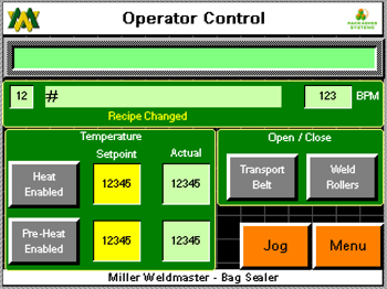
- Top center text box: The text field will list current alarms. The up/down buttons next to the text box will allow the user to scroll up/down the list of current alarms.
- MSG0 text box: The text box field will indicate the current state on the machine. System Idle, System Running, Pause, Forward Job, Conv Door Open, Alarm Active, Reset EPO, Operator Control Side E-Stop, and Non-Operator Control Side E-Stop
- Red indicator light: The red indicator light will display the same color as the stack light in the solid color mode.
- Bag/Min: The “0” indicates the current average bags per minute passing through the machine.
- Feet/Min: “0” indicates the current average bags per minute passing through the machine.
- Weld Nozzle OFF: Pressing the button will toggle the heat system on/off. Press once to toggle to the opposite condition.
- Actual (F): The number displayed is at what temperature the thermo-couple is currently reading at the base of the element housing.
- Setpoint (F): The number displayed is at what temperature the temperature controller is being told to hold the temperature at. By touching the text box on the screen a keypad will appear allowing the user to change the setpoint.
- Pre-Heat Nozzle OFF: Pressing the button will toggle the heat system on/off. Press once to toggle to the opposite condition.
- Weld Roller: Pressing the button will open/close the weld rollers. Press once to toggle to the opposite condition.
- Transport Belt: Pressing the button will open/close the transport belts. Press once to toggle to the opposite condition.
- Jog FWD: Pressing the button will jog the drive system in the forward direction at a slow rate of speed. This function is intended to test the motion of the motors and drive system only. It is not intended to operate in a synchronized function. Jog FWD will only appear when the machine is in a paused state.
- Menu: Pressing the menu button will take the user to the Main Menu screen.
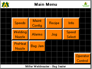
Main Menu Screen, Operator Level
-
- Operator Config: Pressing the Operator Configuration button will take the user to the Operator Configuration, Operator Level.
- Alarms History: Pressing the Alarm History button will take the user to the Alarm History Screen.
- Login: Pressing the Login button will take the user to the Login Screen.
- Logout: Pressing the Logout button will Logout and return user to the base viewable screens.
- Operation: Pressing the Operation button will take the user to the Operator Control Screen.
Operator Configuration, Operator Level
- Recipe Number: The number displayed in the text box is the number of the recipe currently displayed. By touching the text box on the screen a key pad will appear allowing the user to change to the desire recipe number. The up/down arrow located to the right/left of the text box will also adjust to the next recipe. By touching the arrow once the recipe will change to the next recipe.
- Recipe Name: The text displayed is what the current recipe has been named. By touching the text box on the screen a key pad will appear allowing the user to change the text.
- Activate: Pressing the activate button will load the saved setting of the displayed recipe to the appropriate set points. When adjusting a speed setting for example, the speed setting must be changed then the activate button must be pressed in order to send the change to that particular set point.
- Transport Belt (FT/MIN): The number displayed in the text box is the speed at which the Transport Belt is set. The Transport speed is the master speed of the machine. The number is in feet per minute. By touching the text box on the screen a key pad will appear allowing the user to change the Transport belt speed. By touching the arrow once the speed will be increased/decreased by 0.01 ft/min. Once the desired set point has been entered into the text box the user must press the activate button in order to send the change to that particular set point.
- Front Weld Roller (FT/MIN): The number displayed in the text box is at what speed the Front Weld Roller is set. The speed of the Front Weld Roller is a slave to the Transport Speed, but can be offset. The number is in feet per minute. By touching the text box on the screen a keypad will appear allowing the user to change the Front Weld Roller speed. By touching the arrow once the speed will be increased/decreased by 0.01 ft/min. Once the desired set point has been entered into the text box the user must press the activate button in order to send the change to that particular set point.
- Rear Weld Roller: The speed of the Rear Weld Roller is a slave to the Transport Speed. The number is in feet per minute. By touching the text box on the screen a keypad will appear allowing the user to change the Rear Weld Roller speed. The up/down arrow located to the right/left of the text box will also adjust the speed of the Rear Weld Roller. But touching the arrow once the speed will be increased/decreased by 0.01 ft/min. Once the desired set point has been entered into the text box the user must press the activate button in order to send the change to that particular set point.
- Weld Nozzle Temp (F): The number displayed is at what temperature the temperature controller is being told to hold temperature. By touching the text box on the screen a keypad will appear allowing the user to change the Setpoint. The up/down arrow located to the right/left of the text box will also adjust the setpoint. By touching the arrow once the temperature will be increased/decreased by 1’f. Once the desired set point has been entered into the text box the user must press the activate button in order to send the change to that particular set point.
- Pre Heat Temp (F): The number displayed is at what temperature the temperature controller is being told to hold temperature. By touching the text box on the screen a keypad will appear allowing the user to change the Setpoint. The up/down arrow located to the right/left of the text box will also adjust the setpoint. By touching the arrow once the temperature will be increased/decreased by 1’f. Once the desired set point has been entered into the text box the user must press the activate button in order to send the change to that particular set point.
- No Bag Time (SEC): The input bag sensor controls when the nozzle swing system is told to be in the welding position and when to be in the home position when the machine is in run mode. When a bag enters the machine and the sensor sees the bag, the nozzle swing system is told to swing into the weld position. The number displayed in the text box is the amount of time which must pass without a bag passing the input bag sensor. If this amount of time is reached, then the nozzle swing system is told to go to it’s home position until another bag is sensed. By touching the text box on the screen a key pad will appear allowing the user to change the setpoint.
- Save: Pressing the save button will save/resave all of the current setpoint entered into each particular text box to the currently displayed recipe.
- Jog FWD: Pressing the button will jog the drive system in the forward direction at a slow rate of speed. This function is intended to test motion of the motors and drive system only. It is not intended to operate in a synchronized function. Jog FWD will only appear in the paused condition
- Previous: Pressing the previous button will display the previous screen.
Main Menu Screen, SU level:
- Recipe Config: Pressing the Recipe Config button will take the user to the Recipe Configuration Screen.
- Recipe Active: Pressing the Recipe Active button will take the user to the Recipe Active Screen.
- Heat/Manual: Pressing the Heat/Manual button will take the user to the Heat Control Weld Nozzle Screen.
- Machine Config: Pressing the Machine Config button will take the user to the Operator Control Screen.
- Remote Info: Pressing the Remote Info button will take the user to the Remote Info Screen.
- HMI Setup: Pressing the HMI Setup button will take the user to the HMI Setup Screen.
- Alarms Active: Pressing the Alarm Active button will take the user to the Alarm Active Screen.
- Info: Pressing the Info button will take the user to the Info Screen.
- Login: Pressing the Login button will take the user to the Login Screen.
- Logout: Pressing the Logout button will take the user to the base viewable screens.
- SU Maint: Pressing the SU Maint button will take the user to the SU Maintenance Screen.
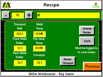
Recipe Configuration Screen
- Recipe Number: the number displayed in the text box is the number of the recipe currently displayed. By touching the text box on the screen a key pad will appear allowing the user to change to the desire recipe number. The up/down arrow located to the right/left of the text box will also adjust to the next recipe. By touching the arrow once the recipe will increased/decreased by 1.
- Recipe Name: The text displayed is what the current recipe has been named. By touching the text box on the screen a key pad will appear allowing the user to change the text.
- Activate: Pressing the activate button will load the saved setting of the displayed recipe to the appropriate set points. When adjusting a speed setting for example, the speed setting must be changed when the activate button must be pressed in order to send the change to that particular set point.
- Transport Belt (FT/MIN): The number displayed in the text box is at what speed the transport belt is set. The Transport speed is the master speed of the machine. The number is in feet per minute. By touching the text box on the screen a key pad will appear allowing the user to change the Transport belt speed. The up/down arrow located to the right/left of the text box will also adjust the speed of the Transport. By touching the arrow once the speed will be increased/decreased by 0.01 ft/min. Once the desired set point has been entered into the text box the user must press the activate button in order to send the change to that particular set point.
- Front Weld Roller (FT/MIN): The number displayed in the text box is at what speed the Front Weld Roller is set. The speed of the Front Weld Roller is a slave to the Transport Speed, but can be offset. The number is in feet per minute. By touching the text box on the screen a key pad will appear allowing the user to change the Front Weld Roller Speed. The up/down arrow located to the right/left of the text box will also adjust the speed of the Rear Weld Roller. By touching the arrow once the speed will be increased/decreased by 0.01 ft/min. Once the desired set point has been entered into the text box the user must press the activate button in order to send the change to that particular set point.
- Rear Weld Roller (FT/MIN): The number displayed in the text box is at what speed the Rear Weld Roller is set. The speed of the Rear Weld Roller is a slave to the Transport Speed, but can be offset. The number is in feet per minute. By touching the text box on the screen a key pad will appear allowing the user to change the Rear Weld Roller Speed. The up/down arrow located to the right/left of the text box will also adjust the speed of the Rear Weld Roller. By touching the arrow once the speed will be increased/decreased by 0.01 ft/min. Once the desired set point has been entered into the text box the user must press the activate button in order to send the change to that particular set point.
- Weld Nozzle Temp (F): The number displayed is at what temperature the temperature controller is being told to hold temperature. By touching the text box on the screen a key pad will appear allowing the user to change the Setpoint. The up/down arrow located to the right/left of the text box will also adjust the set point. By touching the arrow once the speed temperature will be increased/decreased by 1’f. Once the desired set point has been entered into the text box the user must press the activate button in order to send the change to that particular set point.
- Pre Heat Temp (F): The number displayed is at what temperature the temperature controller is being told to hold temperature. By touching the text box on the screen a key pad will appear allowing the user to change the Setpoint. The up/down arrow located to the right/left of the text box will also adjust the set point. By touching the arrow once the temperature will be increased/decreased by 1’f. Once the desired set point has been entered into the text box the user must press the activate button in order to send the change to that particular set point.
-
- Save: Pressing the save button will save/resave all of the current setpoint entered into each particular text box to the currently displayed recipe.
- Jog FWD: Pressing the button will jog the drive system in the forward direction at a slow rate of speed. This function is intended to test motion of the motors and drive system only. It is not intended to operate in a sunchronized function. Jog FWD will only appear in the paused condition.
- Previous: Pressing the previous button will display the previous screen.
Recipe Active Screen
- Recipe Number: The number displayed in the text box is the number of the recipe currently displayed
- Recipe Name: The text displayed is what the current recipe has been named.
- Transport Belt (FT/MIN): The number displayed in the text box is at what speed the transport is set at. The Transport speed is the master speed of the machine. The number is in feet per min.
- Front Weld Roller (FT/MIN): The number displayed in the text box is at what speed the Front Weld Roller is set at. The speed of the Front Weld Roller is a slave to the Transport Speed. The number is in feet per minute.
- Rear Weld Roller (FT/MIN): The number displayed in the text box is at what speed the Front Weld Roller is set at. The speed of the Front Weld Roller is a slave to the Transport Speed. The number is in feet per minute.
- Weld Nozzle Temp (F): The number displayed is at what temperature the temperature controller is being told to hold temperature.
- Pre Heat Temp (F): The number displayed is at what temperature the temperature controller is being told to hold temperature.
- No Bag Time: The input bag sensor controls when the nozzle swing system is told to be in the welding position and when to be in the home position when the machine is in run mode. When a bag enters the machine and the sensor sees the bag, the nozzle swing system is told to swing into the weld position. The number displayed in the text box is the amount of time which must pass without a bag passing the input bag sensor. If this amount of time is reached, then the nozzle swing system is told to go to the home position until another bag is sensed.
- Previous: Pressing the previous button will display the previous screen.
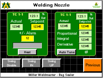
- Actual (F): The number displayed is what temperature the thermo-couple is currently reading at the base of the element housing. By touching the text box on the screen a key pad will appear allowing the user to change the Setpoint.
- Setpoint (F): The number displayed is at what temperature the temperature controller is being told to hold temperature at. By touching the text box on the screen a key pad will appear allowing the user to change the Setpoint.
- Alarm +/- (F): The number display is how many degrees variance is allowed before the high/low temperature alarm is activated.
- Heater Off: By pressing the heater off button the heat system will be toggled off/on. If the heat system is currently off and by pressing the button once the heat system will turn on.
- Heat/Manual #2: Pressing the button will take the user to the Heat Control Pre Heat Nozzle Screen.
- Swing In: Pressing the button will swing the heat system nozzle into its vertical position. Pressing the button a second time will swing the heat system nozzle to its home position. The button is a toggle button and with one.
-
Swing Up: In order for the Swing Up button to become active the heat system swing must be in the vertical position. If not in the vertical position in the Swing Up button will not active. Pressing the button will slide the heat system nozzle into its up position. Pressing the button a second time will slide the heat system nozzle to its down position. The button is a toggle button and with one press of the button the swing system will slide up/down. WARNING! Do not leave the Nozzle in the up position for more than 3 seconds or damage to the weld rollers will occur!
- Jog FWD: Pressing the button will jog the drive system in the forward direction at a slow rate of speed. This function is intended to test motion of the motors and drive system only. It is not intended to operate in a synchronized function. Jog FWD will only appear in the paused condition.
- Auto Tune Proportion: The number displayed is the value of proportional band the temperature controller is currently using for the temperature control loop.
- Auto Tune Integral: The number displayed is the value of Intergral time the temperature controller is currently using for the temperature control loop.
- Auto Tune Derivative: The number displayed is the value of Derivative time the temperature controller is currently using for the temperature control loop.
- Auto Tune: Pressing this button will force the temperature control into an auto tune state. WARNING! Before auto tuning, set the temperature set point to 800’ f and allow the actual temperature become closer to the set point! Not doing so may result in damage to the elements or other heat system components. Auto Tune should only be used when the temperature is fluctuating for an unknown reason. Effort should be exhausted for identifying a faulty component of the heat system, air pressure, air flow, or any other reason before Auto Tune is performed.
- Menu: Pressing the menu button will take the user to the Main Menu screen.
Heat Control Pre Heat Nozzle Screen
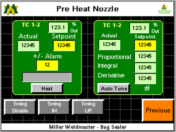
- Actual (F): The number displayed is what temperature the thermo-couple is currently reading at the base of the element housing. By touching the text box on the screen a key pad will appear allowing the user to change the Setpoint.
- Setpoint (F): The number displayed is at what temperature the temperature controller is being told to hold temperature. By touching the text box on the screen a key pad will appear allowing the user to change the Setpoint.
- Alarm +/- (F): The number display is how many degrees variance is allowed before the high/low temperature alarm is activated. By touching the text box on the screen a key pad will appear allowing the user to change the setpoint.
- Heater Off: By pressing the heater off button the heat system will be toggled off/on. If the heat system is currently off and by pressing the button once the heat system will turn on.
- Heater Off: By pressing the heater off button the heat system will be toggled off/on. If the heat system is currently off and by pressing the button once the heat system will turn on.
- Heat/Manual #1: Pressing the button will take the user to the Heat Control Weld Nozzle Screen.
- Swing In: Pressing the button will swing the heat system nozzle into its vertical position. Pressing the button a second time will swing the heat system nozzle to its home position. The button is a toggle button and with one press of the button the swing system will swing in/out.
- Swing Up: In order for the Swing Up button to become active the heat system swing must be in the vertical position. If not in the vertical position the Swing Up button will not activate. Pressing the button will slide the heat system nozzle into its up position. Pressing the button a second time will slide the heat system nozzle to its down position. The button is a toggle button and with one press of the button the swing system will slide up/down. WARNING! Do not leave the Nozzle in the up position for more than 3 seconds or damage to the weld rollers will occur!
- Jog FWD: Pressing the button will jog the drive system in the forward direction at a slow rate of speed. This function is intended to test motion of the motors and drive system only. It is not intended to operate in a synchronized function. Jog FWD will only appear in the paused condition.
- Auto Tune Proportion: The number displayed is the value of proportional band the temperature controller is currently using for the temperature control loop.
- Auto Tune Integral: The number displayed is the value of Intergral time the temperature controller is currently using for the temperature control loop.
- Auto Tune Derivative: The number displayed is the value of Derivative time the temperature controller is currently using for the temperature control loop.
- Auto Tune: Pressing this button will force the temperature control into an auto tune state. WARNING! Before auto tuning, set the temperature set point to 800’ F and allow the actual temperature become closer to the set point!Not doing so may result in damage to the elements or other heat system components. Auto Tune should only be used when the temperature is fluctuating for an unknown reason. Effort should be exhausted for identifying a faulty component of the heat system, air pressure, air flow, or any other reason before Auto Tune is performed.
- Menu: Pressing the menu button will take the user to the Main Menu screen.
Remote Interface Screen
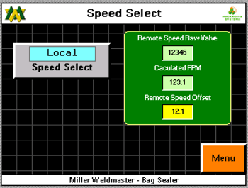
- Speed Control “Local”: Pressing the button will toggle the speed reference stated between Local and Remote. Press once to toggle to the opposite condition.
- Remote SP: The text box will display at what feet per minute the machine is being told to run from the bagger. The machine will run at this speed only when remote speed operation has been selected on the Remote Interface Screen.
- Remote Speed offset (FT/MIN): The number dis- played in the text box reflects the speed entered in order to match the lower conveyor speed with the sealer. By touching the text box on the screen, a key pad will appear allowing the user to change the setpoint. The setpoint can be adjusted to a positive or negative number. For example, if the bag enters the sealer and the bags is standing upright, as the bags travel down line and if the bag begins to lean forward; then the offset is too fast which is telling the sealer to run faster than the lower conveyor. Adjust the setpoint lower and observe the next bag.
- Previous: Pressing the previous button will display the previous screen.
NOTE: It is very important to know that the bag leaning forward or backwards will affect the straightness of the seal. Assuming the bag is straight upon entry; if the bag leans forward as it travels through the sealer this may cause the size of the fold to grow larger from lead-ing edge to trailing edge. If the bag leans backward as it travels through the sealer this may cause the fold to grow smaller from leading edge to trailing edge.
Active Alarm Screen
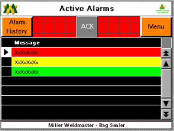
The black text box will diplay and active alarm. These alarms will remain displayed until they have been resolved and the ACK button has been depressed.
- History: Pressing the History button will display the Alarm History screen.
- ACK: Acknowledge alarm, pressing the ACK button will acknowledge the alarm and rest. If the alarm condition has not been resolved the alarm will reappear.
- Previous: Pressing the previous button will display the previous screen.
Alarm History Screen
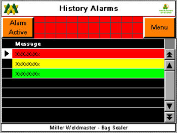
The black text box will display all alarm events which have occurred in the past along with a date and time stamp.
- Up/down arrow buttons: Allow the user to scroll up/down the page of alarms.
- Clear History: Pressing the clear history button will clear what history has been saved in the memory. Clear History button only appear when logged in as SU user.
- Previous: Pressing the previous button will display the previous screen.
Information Screen

This screen is simply to display Miller Weldmaster’s contact information and to provide the machine specific type, serial number, and software version. When calling Miller Weldmaster for questions of any kind, please have the machine type, serial number, and software version to provide to the Miller Weldmaster representative.
- Previous: Pressing the previous button will display the previous screen.
Login Screen
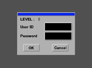
In order to access locked or leveled access screens the appropriate User ID and Password must be entered. Please contact your supervisor with any questions at all.
Machine Configuration Screen
- Jog Speed (FT/MIN): The number displayed reflects how many feet per minute the drive system will operate when the jog button is depressed. By touching the text box on the screen a key pad will appear allowing the user to change the jog speed.
- Pause Delay Time (SEC): The number displayed is how much time will pass after a pause signal has been given or a pause button is pressed. This function is to allow the PS400 system to be cleared of bags. By touching the text box on the screen a key pad will appear allowing the user to change the Pause Delay Time.
- Bag Jam Time (SEC): The number displayed is of how many seconds will pass once a bag is viewed by the input bag sensor and when the bag jam alarm will be set if a bag is not viewed by the output bag sensor. For instance, when a bag enters the machine, assuming correct presentation, the input bag sensor will see the bag and likewise when the bag exits the machine the output bag sensor will see the bag. By touching the text box on the screen a key pad will appear allowing the user to change the Bag Jam Time.
- Swing In Time and Swing Out Time(SEC): The nozzle swing system is designed with two motions and two air cylinder making the motions. From the home position, the nozzle pivots toward the weld rollers then slides up; and from the weld position, the nozzle slides down then pivots out. This design has been created to allow the nozzle position to be in close proximity to the guide system, weld roller, and the bag itself.
- Swing In Time (Sec): The number displayed is the amount of time the second action of the nozzle swing system. For example when the nozzle swing is told to actuate, the pivot action begins immediately but the second action, slide, up does not begin until the time has reach set point. This amount of time is to allow the pivot of the nozzle to be in place directly below the weld rollers and guide before beginning to slide up. By touching the text box on the screen a key pad will appear allowing the user to change the Swing In Time.
- Swing Out Time (SEC): The number displayed is the amount of time the second action of the nozzle swing system. The action and sequence of events is the exact reverse of the Swing In Time. By touching the text box on the screen a key pad will appear allowing the user to change the Swing Out Time.
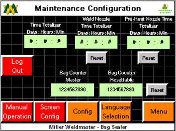
- Element Advisory Snooze (HRS): Once an end of life advisory has become active and the ACK button is depressed the end of life advisory enters a snooze mode. The number displayed is how many hours of snooze. The amount of hours is adjustable between 0 and 99 hours. By touching the text box on the screen a keypad will appear allowing the user to change the number of hours.
- Machine: Total amount of time the machine is powered on. Time is displayed in hours.
- Weld Nozzle: Total amount of time the Weld Heat system is powered on. Time is displayed in hours.
- Pre-Heat Nozzle: Total amount of time the Pre Heat system is powered on. Time is displayed in hours.
- Bag Counter: Total number of bags which has passed by both the input and output bag sensors.
- Weld Nozzle Active Element (HRS): Total amount of time the weld nozzle is powered on since last reset.
- End of Life Advisory: The number displayed is after how many hours the heat system is powered on until the END of Life Advisory will be displayed. The advisory can be acknowledge but pressing the back button, which will then reset the advisory for 24 hours. The End of Life message will continue until an authorize person logs into the SU user and resets both the weld nozzle and preheat nozzle hour meter. The amount of hours is adjustable between 0 and 99 hours. By touching the text box on the screen a keypad will appear allowing the user to change the number of hours.
- Pre-Heat Nozzle Active Element: Total amount of time the weld nozzle is powered on since last reset.
- Bag Counter Resetable: Total number of bags which has passed by both the input and output bag sensors. By pressing the reset button the value in the totalizer will reset to zero.
- Previous: Pressing the previous button will display the previous screen.
Setting Speeds
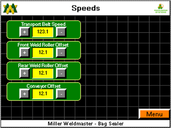
- Transport Belt (FT/MIN): The number displayed in the text box is the speed at which the the Transport Belt is set at. The Transport speed is the master speed of the machine. The number is in feet per minute. By touching the text box on the screen a key pad will appear allowing the user to change the Transport belt speed. The up/down arrow located to the right/left of the text box will also adjust the speed of the Transport Belt. By touching the arrow once the speed will be increased/decreased by 0.01 ft/min. Once the desired set point has been entered into the text box the user must press the activate button in order to send the change to that particular set point.
- Front Weld Roller (FT/MIN): The number displayed in the text box is at what speed the Front Weld Roller is set. The speed of the Front Weld Roller is a slave to the Transport Speed, but can be offset. The number is in feet per minute. By touching the text box on the screen a key pad will appear allowing the user to change the Front Weld Roller Speed. The up/down arrow located to the right/left of the text box will also adjust the speed of the Rear Weld Roller. But touching the arrow once the speed will be increased/decreased by 0.01 ft/min. Once the desired set point has been entered into the text box the user must press the activate button in order to send the change to that particular set point.
- Rear Weld Roller (FT/MIN): The number displayed in the text box is at what speed the Rear Weld Roller is set. The speed of the Rear Weld Roller is a slave to the Transport Speed, but can be offset. The number is in feet per minute. By touching the text box on the screen a key pad will appear allowing the user to change the Rear Weld Roller Speed. The up/down arrow located to the right/left of the text box will also adjust the speed of the Rear Weld Roller. By touching the arrow once the speed will be increased/decreased by 0.01 ft/min. Once the desired set point has been entered into the text box the user must press the activate button in order to send the change to that particular set point.
- Weld Nozzle Temp (F): The number displayed is at what temperature the temperature controller is being told to hold temperature. By touching the text box on the screen a key pad will appear allowing the user to change the Setpoint. The up/down arrow located to the right/left of the text box will also adjust the set point. But touching the arrow once the temperature will be increased/decreased by 1’f. Once the desired set point has been entered into the text box the user must press the activate button in order to send the change to that particular set point.
- Pre Heat Temp (F): The number displayed is at what temperature the temperature controller is being told to hold temperature. By touching the text box on the screen a key pad will appear allowing the user to change the Setpoint. The up/down arrow located to the right/left of the text box will also adjust the set point. But touching the arrow once the temperature will be increased/decreased by 1’f. Once the desired set point has been entered into the text box the user must press the activate button in order to send the change to that particular set point.
Manual Menu Screen
![]() This is a test tool for technicians only. Before you engage an output make sure that it is safe to perform the action. Otherwise harm could come to the operator or machine. Machine must be in manual mode to perform these test!
This is a test tool for technicians only. Before you engage an output make sure that it is safe to perform the action. Otherwise harm could come to the operator or machine. Machine must be in manual mode to perform these test!
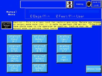
Current Manual Off

Pressing this button will toggle the machine function from manual on/off.
Manual Input View 0-7
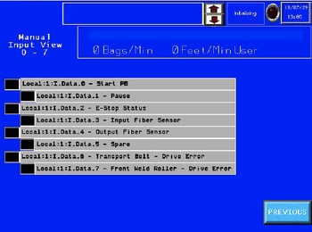
The black box next to the text will illuminate when the input is on. This is a viewable screen only. Reference the electrical schematic and the text written on the screen to insure the desired input is being turned on/off.
Manual Input View 8-15
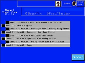
The black box next to the text will illuminate when the input is on. This is a viewable screen only. Reference the electrical schematic and the text written on the screen to insure the desired input is being turned on/off.
Manual Input View 13-23
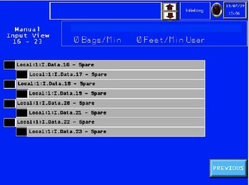
The black box next to the text will illuminate when the input is on. This is a viewable screen only. Reference the electrical schematic and the text written on the screen to insure the desired input is being turned on/off.
Manual Input View 23-31
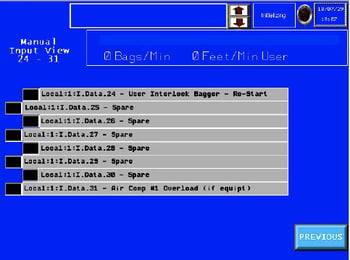
The black box next to the text will illuminate when the input is on. This is a viewable screen only. Reference the electrical schematic and the text written on the screen to insure the desired input is being turned on/off.
Manual Analog Input View
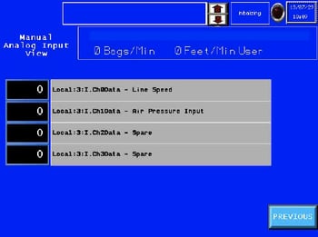
The black box will display the engineering data coming in to the input. This is a viewable screen only. Reference the electrical schematic and the text written on the screen to insure the desired input is displaying the data.
Manual Analog Output View
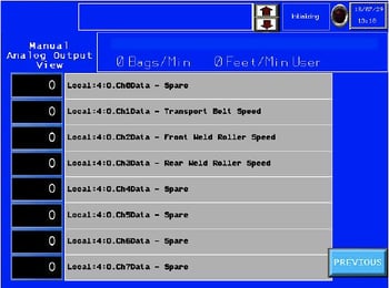
The black box will display the engineering data coming in to the output. This is a viewable screen only. Reference the electrical schematic and the text written on the screen to insure the desired output is displaying the data.
Manual HSC Input View
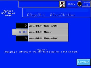
The number displayed is the engineering counts of the high speed counter. This is a viewable screen only.
Manual Output 0-7
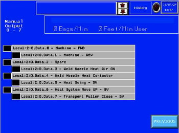
By touching the black box on the screen next to the output, the output will turn on/off. Reference the electrical schematic and the text written on the screen to insure the desired output is in fact being turned on/off.
Manual Output 8-15
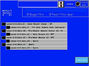
By touching the black box on the screen next to the output, the output will turn on/off. Reference the electrical schematic and the text written on the screen to insure the desired output is in fact being turned on/off.
Manual Output 16-23
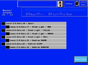
By touching the black box on the screen next to the output, the output will turn on/off. Reference the electrical schematic and the text written on the screen to insure the desired output is in fact being turned on/off.
Manual Output 24-31
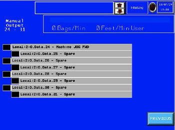
By touching the black box on the screen next to the output, the output will turn on/off. Reference the electrical schematic and the text written on the screen to insure the desired output is in fact being turned on/off.
Features
- Suitable for multiple-sized Polywoven bags with several bag closure styles.
- User Friendly HMI allows the operators to easily adjust the machine for a wide variety of products.
- Auto-Control Temperature controller allows the system to accurately provide heat to the products being produced.
Technical Specifications
- Amp Rating = 30amp at 230volt / 30amp at 480 volt
- Rated Power = 9000 W
- Rated Voltage = 230v AC, 50/60hz or 480v AC, 50/60hz
- Maximum Temperature = 1472°F (800°C)
- General Air Pressure = 100psi (6.9 bar)
- Machine Speed = 20 ft/min to 150 ft/min (6 m/min to 45 m/min)
- Overall Dimensions = 116in long x 54in wide x 68in tall (2946mm x 1372mm x 1727mm)
- Seal Width = 1in to 2in (25mm to 50 mm)
- Maximum Noise = 75 dbA
- Electrical Document Number: MWC-0100-1200 (The documentation number is the serial number of the machine. This number is located on the serial tag on the machine.)
Technical Specifications
Mechanical Section
Heat Source
- Hot Air - heat element housing contains the heating element and thermal-couple.
Upper/Lower Unit
- Upper Weld Roller, located towards the front of the machine, moves horizontally to open and close the weld rollers.
- Lower Weld Roller, located towards the rear of the machine, is stationary.
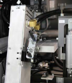
Heat System Adjustment Assembly
- Allows for accurate positioning of the Hot Air Nozzle.
Guide System
- Used to create the fold of the bag closure.
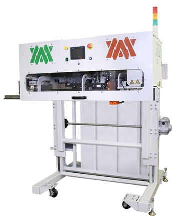
Operator Controls Section
Control Panel (Reset Button, Pause Button, Emergency Stop)
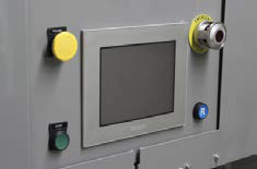
Control Panel: The HMI (Human Machine Interface) Digital Touch Screen allows you to set system controls.
Reset Button: Pushing will allow operation at machine start up or after the emergency stop has been depressed.
Pause Button: The pause button, when depressed, will bring the machine to a controlled stop.
Emergency Stop: The emergency stop button (Estop) , when depressed, will set the machine into an emergency stop condition. Heat will be turned off, motors will stop, and nozzle will go to home position. The condition for emergency stop must be cleared, the machine must be inspected to see if ready to reset, then the reset button can be depressed.
Pneumatic System
Inlet Air Filter and Water Separator
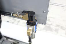
Filters out water and dirt in the air.
Pressure Gauge
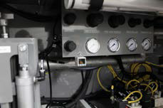
Used for displaying the pressure setting. The Weld Roller gauge is used for displaying the pressure setting of the Weld Roller for example.
Air Cylinder / Solenoid Valves
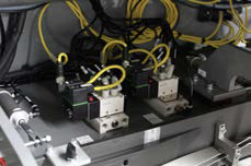
Air Cylinder: The upper unit/transport Air Cylinders are used for opening and closing the weld roller and transport belt. The heat system cylinder controls swing-in and swing-out of the heat system.
Solenoid Valves: several solenoid valves are used for the operation of air cylinders, welding air and chillers.
![]() Warning! The operator must disconnect the power from the machine before proceeding.
Warning! The operator must disconnect the power from the machine before proceeding.
- Loosen and remove the protective cover from the element housing.
- Unpack the fiberglass insulation around the front of the element housing. Be cautious to avoid eye contact when handling the insulation.
- Loosen and remove the two bolts to the bracket holding the element housing in place.
- Remove the bolt securing the element in the housing.
- Loosen the 2 upper set screws (1 on each side) on the element securing the electrical leads and remove the leads.
- Pull out the element vertically
- Replace the old element with a new element by following the procedure in reverse. When reinstalling the element, be sure to align the key to the slot of the element housing to the element
NOTE: The Quartz tube is easily broken and can already be broken, be very careful.
Maintenance
Electrical Circuits
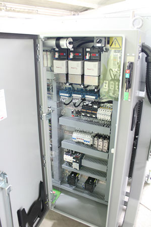
- When replacing parts and components, you must use the part or components of the same type as the original type. Original equipment replacement parts should be purchased through Miller Weldmaster and or a Miller Weldmaster authorize distributor.
- The electrical cabinet must be cleaned every three months. To properly clean the electrical cabinet: dis connect the power supply, using compressed air and a blow gun, gently blow air across the electrical component and control cabinet cleaning dust and debris from the area.
- To avoid damaging the PLC, Display and Operating Panel, never plug or unplug the cables connecting the PLC, Display and Operating Panel while the power is on.
- If there is any fault that cannot be removed, please immediately contact the service department at Miller Weldmaster.
Direct Drive
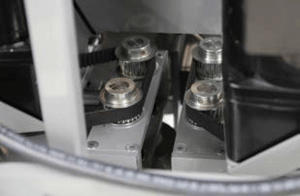
- Check if the Driving sprockets and belts for proper alignment, wear, and secure to the shaft.
- Check if belts are too loose. Tighten as needed.
- Check if the nozzle is parallel with and at the center of the Weld Roller. If not, it shall be adjusted as per section 3.3.1.
- Check if the open/close movement of the weld roller unit and transport is smooth.
NOTICE: By not properly maintaining the machine, the performance may be effected. Please contact Miller Weldmaster with any questions.
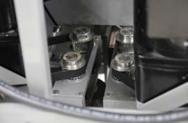
Maintaining Belts and Pulleys
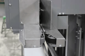
- The Miller Weldmaster PS150 has several belts and pulleys that are used to drive weld rollers, creaser, trimmer, and transport system. Although not a high maintenance item, belts and pulleys should be inspected once a month to ensure there is not excessive dust, or dirt. Also inspect for any looseness or slack. For newly installed machines the belts and pulleys should be inspected once per week for the first two weeks of operation.
- Turn the circuit breaker to the off position.
- Disconnect the power cord from the power supply. If the power cord is hard wired, shut the power supply off at the junction box.
- Open both cabinet doors and inspect the belts and pulleys. Perform any maintenance to the belts and pulleys as needed.
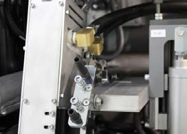
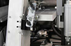
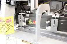
Machine Adjustments
(Fig. 55) (Fig. 56) (Fig. 57) (Fig. 58) (Fig. 59)
Begin by turning your hot air on and setting to the desired temperature. Set weld rollers to the closed position by engaging the Weld Roller button on the HMI.
NOTE: Manual swing buttons are located of the HMI screen “Heat Control Weld Nozzle” or “Heat Control Pre Heat Nozzle”
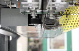
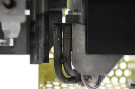
- Left to right nozzle position, check left/right nozzle po- sition by engaging the “Swing In” button on the HMI. The nozzle should be centered on the Guide nose pieces (see fig 57), if so, move on to next alignment step. If not, locate the left to right adjustment bolt jam nut and loosen (see fig 55). This will allow adjustment of the left to right nozzle position. Rotating the left to right adjustment bolt (see fig 55) clock wise/counter clock wise the nozzle position will move the nozzle tip to the left or right. After the nozzle is centered on the Guide nose pieces, tighten down the jam nut.
- Up and down nozzle position, check this by engaging the “Swing Up” button on the HMI. The tip of the nozzle should be positioned 1/16” to 1/8” below the top of the Guide nose pieces (see fig 58), if so move on to the next alignment step. If not locate the height adjustment knob and loosen the jam nut (see fig 56). This will allow us to adjust the height of the nozzle position will move the nozzle tip to the up or down. After the nozzle is 1/16” to 1/8”below the top of the Guide nose pieces, tighten down the jam nut.
- Depth of your nozzle should be at approximately 1/16 - 1/8 of an inch from the pinch point of your weld rollers and with a minimal gap between the Pre Heat nozzle and the nose pieces (see fig 58). Check depth nozzle position by engaging the “Swing In” and “Swing Up” button on the HMI. If the nozzle is aligned, perform a test weld. If the nozzle depth is not aligned locate the depth adjustment slots and loosen the bolts (see fig 59). Once the bolts are loosened then the entire heat system can be moved forward or backward to properly align the nozzle. When the nozzle is aligned, perform a test weld.
NOTE: Nozzle tip will move up/down or right/left when heat is changed. After a heat change of more than 200 degrees, be sure to check position of nozzle tip.
WARNING! When nozzles are at desired temperature and the nozzles are manually located in the weld position, damage to the weld rollers will occur!
Adjusting the Height of the Machine
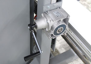
(Fig. 60) (Fig. 61)
- The height of the machine is adjusted by the crank handle
- By flipping the ratchet selector switch, the user can adjust the height up/down. (see fig 60)
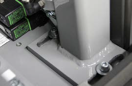
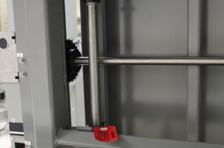
WARNING! Do not attempt to adjust the height of the machine higher than the maximum limit. Located next to the height adjustment crank is a height scale. At the top of the scale the user will find a red zone. Do not adjust the height of the machine inside the red zone. Damage to the machine or injury to the user may occur if the machine is adjusted higher than its maximum limit! - Once the machine has been adjusted to the desired operating height the two lower limit clamping collars must be adjusted in order to limit the down stroke of lift system. (fig. 61)
- The user will find a red reminder tag on near the clamping collars used to limit the down stoke of the lift system. (fig. 61)
Transportation and Storage
WARNING! It is recommended to use a forklift when moving or removing a crated machine from a pallet. It is recommended to use a forklift when moving the machine through the plant. It is very important that the height adjustment of the machine is taken to its lowest point prior to the machine being moved at all!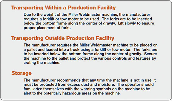
NOTE: The manufacturer will not be held liable for any damage or injuries occurring from any inappropriate use of this machine.
Technical Requirements
- Total air pressure should be 100 psi (6.9 bar) at a minimum and 150 psi (10.3 bar)
- The pressure of the weld rollers should be between 40 psi and 50 psi (2.8 bar and 3.4 bar).
- The open and close of Weld Rollers and transport belts must be smooth and free, without obvious vibration.
- When the Upper/Lower Weld Rollers are aligned properly, the edges of the two rollers should be parallel and aligned.
- Heat System Swing: The swing in/out of the heat system should be smooth and natural at moderate speed.
- Air lines and air fittings should be free of leaks.
- All serviceable bearings and bearing block should be inspected once per month and greased as needed. During 24 hour operation 5 to 7 days per week a small amount of grease may be requires once per month.
- Nozzle position must be check at the beginning of each shift & after any bag jams near the nozzles.
NOTICE
Changes in factors such as thickness of materials, qualifications of the operators and different environment and weather may directly affect the product. The operator should be able to understand the following adjustable factors particularly:
- Heating Temperature
- Air Pressure
- The pressure of the Upper Weld Roller
- Air volume
- Placement of heating system
14.0 Additional Machine Documents