This instruction manual is intended to be a guide when operating the RFlex Travel Extreme. To ensure optimal performance from your welder, please follow the recommendations and specifications precisely.
Table of Contents
- Chapter 1: Intended Use
- Chapter 2: Safety Signs and Pictographs
- Chapter 3: Technical Data
- Chapter 4: Technical Description
- Chapter 5: Assembly and Installation
- Chapter 6: Operation
- Chapter 7: Selection Of Weld Parameters
- Chapter 8: Maintenance
- Chapter 9:
Occupational Health & Safety
- Chapter 10: Electrical Documentation
- Chapter 11: Pneumatic Documentation
- Chapter 12: General Instructions
- Chapter 13: Appendices
- Chapter 14: Additional Machine Documents
For more technical information regarding this machine call our Resolution Center at 1-855-888-WELD or email service@weldmaster.com.
1.0 Machine Overview/Intended Use
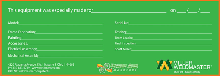
Miller Weldmaster is a leading company in traveling head high frequency welding machines. Traveling Head RFlex welder is designed specifically for production of large format tarpaulins, tents, shading systems, truck covers, swimming pool covers, airline hangars, billboards, signs, side curtains and many other general technical fabric joining. Machine can be fitted with special curved electrodes for welding round window profiles made of clear PVC and any other shapes requiring precision sealing.
RFlex Travel model is equipped with special high precision linear motion gear, controlled by frequency inverter and glide-on railing to achieve a perfect continuous straight line seam. Work table has gutter for easy material handling. Optional vacuum work table with the length up to 12 meters and laser guides allow handling of large format materials and precision weld positioning for fast production setup.
With the use of touch screen HMI and programmable PLC operator can easily input multiple weld/seam recipes. RFlex Travel welding machine have RF power outputs for heavy production load and reinforced heavy duty fabrics.
Automatic weld cycles, pneumatically driven welding bar, electronic motion counter controlling the length, traveled distance and weld cycle number make this machine a perfect tool for high end product where precision, durability and strength is the key.
RFlex Travel can be easily upgraded and converted into a Keder production machine with the use of special attachment and weld electrode.
THE MOST IMPORTANT MACHINE FEATURES:
- the machine routine maintenance is very simple;
- the pressing can be precisely adjusted;
- the manufacturer installed the emergency button on the control panel;
- the machine is equipped with the signal light column so as to enhance the operator’s safety when the machine is on;
- the operator can programme and control the machine’s duty cycle due to the HMI touch-sensitive panel;
- the programming tool enables the operator to enter in the system such parameters as: the weld time and power along with the cooling time;
- using the HMI panel installed on the machine the operator can save many weld programmes for different kinds of materials, let alone the ones used for work with different types of electrodes;
- for the operator’s convenience the machine is equipped with the electrode holder especially designed for a quick change of the welding electrode;
- the machine is fitted out with the additional grounding electrode so as to protect the user against the increased level of HF non-ionizing radiation emitted by the machine;
- ZTG RF AutoTuning System™ - the machine is equipped with the automatic output power control system in order to increase the operator’s safety;
- ZTG SafeDOWN™ - the machine is furnished with the system which should effectively protect the operator against the electrode when it is being lowered;
- ZTG Flash™ - another machine’s system which is supposed to protect the electrode and the raw material being welded from the possible damage caused by an arc-over;
- All machines have received the CE Certificates of Conformity
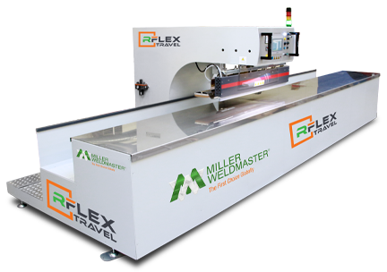
HIGH FREQUENCY TECHNOLOGY:
High Frequency Welding, known as Radio Frequency (RF) or Dielectric welding, is the process of fusing materials together by applying radio frequency energy to the area to be joined. The resulting weld can be as strong as the original materials.
HF Welding relies on certain properties of the material being welded to cause the generation of heat in a rapidly alternating electric field. This means that only certain materials can be welded using this technique. The process involves subjecting the parts to be joined to a high frequency (most often 27.12MHz) electromagnetic field, which is normally applied between two metal bars. These bars also act as pressure applicators during heating and cooling. The dynamic electric field causes the molecules in polar thermoplastics to oscillate. Depending on their geometry and dipole moment, these molecules may translate some of this oscillatory motion into thermal energy and cause heating of the material. A measure of this interaction is the loss factor, which is temperature and frequency dependent.
Polyvinylchloride (PVC) and polyurethanes are the most common thermoplastics to be welded by the RF process. It is possible to RF weld other polymers including nylon, PET, PET-G, A-PET, EVA and some ABS resins, but special conditions are required, for example nylon and PET are weldable if preheated welding bars are used in addition to the RF power.
HF welding is generally not suitable for PTFE, polycarbonate, polystyrene, polyethylene or polypropylene. However, due to the impending restrictions in the use of PVC, a special grade of polyolefin has been developed which does have the capability to be RF welded.
The primary function of HF welding is to form a joint in two or more thicknesses of sheet material. A number of optional features exist. The welding tool can be engraved or profiled to give the entire welded area a decorative appearance or it can incorporate an embossing technique to place lettering, logos or decorative effects on the welded items. By incorporating a cutting edge adjacent to the welding surface, the process can simultaneously weld and cut a material. The cutting edge compresses the hot plastic sufficiently to allow the excess scrap material to be torn off, hence this process is often referred to as tear-seal welding.
 ATTENTION: The manufacturer will not be held liable for any damage or injuries occurring from any inappropriate use of this machine.
ATTENTION: In order to use the machine an optimum and safe way, please read carefully and follow all the instructions included in this Operation & Maintenance Manual.
ATTENTION: All operatives, trained in operational safety, operating procedures and welding machine risk, as well as those qualified to operate the welding machine, are requested, by the Contractor, to sign, with their legible signature, the attached form.
ATTENTION: The high frequency welding machine was designed and produced in a version which is unsuitable for persons with disabilities. Where the machine is to be operated by disabled persons, the machine should be properly adapted after consultation with the manufacturer.
2.0 Safety Signs and Pictographs
2.1 General Information
In order to use the welder in an optimum and safe way, please read carefully and follow all the instructions included in this Operation & Maintenance Manual, also particularly all warning, prohibition, restriction and order information and signs.
On the basis of the information included in this Operation & Maintenance Manual, the Client must elaborate Workstation Manuals for employees.
The Client is fully, legally and materially liable for any and all events resulting from insufficient knowledge of this Operation & Maintenance Manual or failure to conform to the principles of the Occupational Health & Safety.
WARNINGS PUT ON THE DEVICES AND/OR DESCRIBED IN SUBSEQUENT Operation and Maintenance Manual BEING ACQUAINTED WITH THEM IS STRICTLY OBLIGATORY.  ATTENTION: Before getting into any work of any person operating HF welding machine it is obligatory to become acquainted with the subsequent Operation and Maintenance Manual.
ATTENTION: Any receiver or person authorized by the receiver on the basis of the hereby Operation and Maintenance Manual and proper characteristic of production-technology is obligatory due to issue WORKSTAND MANUAL for operators.
ATTENTION: High frequency welding machine can be operated ONLY by workers that have been trained in servicing the device and INDUSTRIAL SAFETY with the special consideration of possible risk coming from the machine.
ATTENTION: During the whole working life of the machine, the device Manufacturer suggests to the Purchaser using the trained service personnel provided by the Manufacturer or any service teams authorized by the Manufacturer.
ATTENTION: Manufacturer strongly recommends to install the welding machine only in industrial environment.
ATTENTION: The machine must be properly levelled and must have fixed place of a operation.
ATTENTION: Careless handling of the machine during transportation (moving) may result in serious injuries or accidents.
 ATTENTION: The generator is powered by the dangerous for life voltage of power grid 3 x480 VAC; 50 Hz. The device has the high voltage up to 8000 VDC. All service or prevention activities can be executed only by the trained personnel with the authority required by the law.
ATTENTION: Purchaser should necessary take care of proper execution and regular prevention control of anti-electric shock protection installation for each device that is in use. All responsibility in this matter is on the Purchaser 's side.
ATTENTION: The lamp voltage must be the same as specified in the datasheet of the product – it is possible to adjust it using branches on the primary side of the incandescent transformer.
ATTENTION: The lamp must be preheated for about an hour after the installation.
 ATTENTION: Any work in within the zone of active pressing unit of the press, ie. device replacement can be executed with special precaution measurements only by trained service team.
 ATTENTION: Emergency stop of the machine is possible at any moment by pressing the EMERGENCY STOP button (the red button on yellow background).
 ATTENTION: The working environment of the machine, the floor and the manual holders and grips must be always clean and free of any contamination, grease or mud, in order to reduce the risk of slipping or falling to the minimum possible level.
CAUTION: Unplug machine before removing any access panels or opening doors. All guards and access panels must be in place before operating this machine.
 ATTENTION: The temperature of the electrode is up to 100 °C. Therefore, when touched one can be burnt.
 ATTENTION: The lamp contains rare-earth metals and rare-earth metal oxides that are highly toxic. In the event of breaking, the lamp must be disposed with utmost care and with the help of specialized services.

 ATTENTION: High frequency welding machine is the source of non–ionic electromagnetic radiation. After installation of machine at buyer's place, non-ionic radiation measurement must be done. The radiation measurements should be done by authorized company.
 ATTENTION: High frequency welding machine must work in a firm working place as transposition requires new measurement of non-ionic radiation intensity.
 ATTENTION: It is forbidden for people with implanted pacemaker to stay in the zone of active radiation.
ATTENTION: Manufacturer suggest not to employ any pregnant or nursing woman in the zone of active non-ionic radiation.
ATTENTION: Clear air filter in pneumatic installation at least once a month.
 ATTENTION..! There are laser indicators in the device. Under no circumstances should the laser beam be directed towards the eyes as it can cause temporary blindness or, in extreme cases, permanent sight damage.
 IT IS FORBIDDEN to execute any work at the welder by people without being previously trained in high frequency machine service and Industrial Safety regulations with the special consideration of possible risk coming from the machine.
  IT IS FORBIDDEN to turn on the machine by workers without being previously trained in service and Industrial Safety regulations.
  IT IS FORBIDDEN to turn on the machine by workers without being previously trained in service and Industrial Safety regulations.
  IT IS STRICTLY FORBIDDEN to execute any service or prevention work without previously disconnecting the generator and machine from power supply.
 IT IS STRICTLY FORBIDDEN to take up any attempts to touch electrodes or elements of pressing unit in press. Touching them while welding or may cause burns by high frequency current or high temperature ~ 100 oC. IT IS STRICTLY FORBIDDEN to take up any actions that can decrease safety status of the machine, ie. working with open protection cover, blocking key buttons, etc.IT IS FORBIDDEN for pregnant or nursing woman to stay in the zone of active non-ionic radiation.
 IT IS STRICTLY FORBIDDEN for people with implanted pacemaker to stay in the zone of active non-ionic radiation.
 IT IS FORBIDDEN for people with metal-orthopedic implant to stay in the zone of active non-ionic radiation.
 IT IS FORBIDDEN to bring in the zone of active non-ionic radiation metal tools.
 IT IS STRICTLY FORBIDDEN to fight any fire at the generator and machine using water or other liquid.
 IT IS STRICTLY FORBIDDEN to remove protection covers while the machine is operating.
 IT IS STRICTLY FORBIDDEN to hose down the machine during operate or go down the system.
 IT IS FORBIDDEN to pour away oils, solvents or other toxic liquiud waste in the surroundings of operating machine.
 IT IS FORBIDDEN to use the cellphone in the surroundings of operating machine.
 IT IS FORBIDDEN to use fire in the surroundings of operating machine.
 IT IS FORBIDDEN to smoke in the surroundings of operating machine.
 IT IS FORBIDDEN to drink the alcohol in the surroundings of operating machine and operate all the devices by drunk workers.
 IT IS FORBIDDEN to consume in the surroundings of operating machine.
 IT IS OBLIGED to train each person that is to execute any work at the generator and press in machine service and Industrial Safety regulations with the special consideration of possible risk coming from the machine.
 IT IS STRICTLY OBLIGED to use ALL designed protection covers and blocking key buttons.
 IT IS OBLIGED to inform the supervisor and / or traffic personnel about any and all cases of incorrect operation of the machine.
 IT IS OBLIGED to use work clothes with minimal parts that can be caught or dragged by the press from high frequency machine.
 IT IS OBLIGED to execute any work on welder elements (electrode, pressing unit) using special protection gloves.
 IT IS OBLIGED to use anti slide work shoes by workers.
 IT IS OBLIGED to use headgear by workers.
 IT IS OBLIGED to keep the floor clean in the surroundings of operating machine.
 IT IS STRICTLY OBLIGED to operate the welding machine by workers trained in high frequency machines service and Industrial Safety regulations.IT IS OBLIGED to immediately turn off the machine cases of incorrect operation using EMERGENCY STOP button.IT IS STRICTLY OBLIGED to disconnect the generator and machine from any supply media before taking up any service or prevention work.IT IS STRICTLY OBLIGED to discharge ceramic capacitors in high frequency generator. Even after being disconnected, they can maintain charge at voltage of several thousand Volt which can cause danger to life.
 The lamp must be always transported or moved in the original manufacturer’s packaging, in vertical position, with anode directed to the top or bottom, without any hitting or shaking the lamp.
3.0 Technical Data
|
Machine type |
RFlex Travel |
|
Welding materials |
PVC, PVC coated fabrics |
|
Power supply |
3 x 220 V; 50/60Hz |
|
PLC driver |
Delta |
|
Control voltage |
24 VDC |
|
Installed capacity |
22 kVA |
|
RF Power Output |
15 kW |
|
Output capacity adjustment |
manual/autotuner |
|
Operating frequency |
27,12 MHz |
|
Frequency stability |
+/- 0,6 % |
|
Antiflash system, ZEMAT TG |
ultra-fast sensitive ARC sensor |
|
Compressed air consumption |
70 nl/cycle |
|
Compressed air pressure |
0,4-0,8 MPa |
|
Max. electrode length |
1500 mm |
|
Work table size |
1620 x 320 mm |
|
Actuator stroke |
160mm |
|
Pressing electrode drive |
pneumatic |
|
Pressure force (max) |
1900 kG |
|
Generator lamp |
ITL 12-1 |
|
Coolant |
air |
|
Machine weight |
~ 1600 kg |
|
Dimensions |
SEE APPENDICES |
4.0 Technical Description
Radio Frequency Welder RFlex Travel consists of the following basic elements:
- WELDING HEAD – with a support frame made of welded steel sheets and shaped profiles. The internal part of the construction can be divided into three zones:
- a rear part - where a high frequency generator is located with an anode transformer and a control cabinet. This part is protected by removable covers equipped with limit switches;
- a welding zone – with working table. The weld is made by an electrode pressed down to the bench by an insulated tool grip connected to a pneumatic actuator by an intermediate plate and insulators. The welding zone is protected from non-ionizing radiation by the movable grounding electrode which is pressed against the table during the weld procedure and as a result a kind of capacitor which is supposed to limit the non-ionizing radiation is created. Particular attention should be paid to the fact that the surface of the material to be welded is evenly distributed on the work table and is not corrugated. Particular attention should be paid that there are no metal objects near the grounding electrode and under it. Failure to comply with the conditions in the above two warnings may affect the emission of the electromagnetic field. Over the welding zone there is an operator’s panel where most of the device controls are placed. In addition, the machine has been equipped with an additional electrode, enabling welding without the use of grounding electrode. After installing this kind of electrode in the holder and starting to lower it, an additional limit switch is activated, which inhibits the movement of the grounding electrode.
- the drive of the machine is located in the lower part of the contraction. It consists of an asynchronous motor connected with a rack via rack transmission. The motor is controlled by an inverter placed in the control cabinet on the machine's chassy. The rack moves on a chain fixed to the table assembly. The machine's trajectory is controlled by rails on which sliding or wheel carriages move.
|
|
 ATTENTION! The protective housing of the machine’s chassy, together with the installed key limit switches minimize the emission of the non-ionizing, electro-magnetic energy. It is strictly FORBIDDEN to work on the HF welder without these protective devices!!
- WORKING TABLE with a trough – made of interconnected aluminum profiles to provide appropriate rigidity. In the front section, the work table is fixed on a steel profiles which are the base for the runners (rails) on which the machine moves. In the rear, the work table is supported by folding posts which fold down during the machine's passage along the rails. On both ends of the work table, there are adjustable bumper switches which activate the limit switches marking the beginning and the end of the work table as well as two elastic buffers which, in the case of break-down, stop the machine at the end of the work table protecting against damage. Electric and pneumatic power is supplied to the HF welding head via cables placed in flexible cable guides. The electric and pneumatic connections are situated in the centre of the rear of the work table.
The following systems of the machine can be distinguished:
- THE CONTROL SYSTEM consisting of a PLC with a touch-panel HMI, control-handling elements placed on a control panel and electric and electronic assembly placed in the control cabinet and inside the machine chassy.
- THE COMPRESSED AIR SYSTEM consisting, among others, of a compressed air preparation assembly, distribution valves, reduction valves and pneumatic cylinders.
- THE RF GENERATION SYSTEM consisting of a self-activating, high frequency generator with distributed constants with a high-Q LC circuit oriented to a resonance frequency of 27.12MHz. The system also includes a triode, HF generating tube, anode and filament transformers as well as a cooling system of the HF generation tube.
The welding electrode holder is equipped with an automatic grip system controlled from the HMI touch-panel. It allows for the tool free replacement of electrodes.
|
|
The machine has built in system (ZTG AntiCRUSH) designed to protect the operators' hands against crushing. When a hand or any object with a height different from the height of the welded material is placed under the welding electrode, the electrode is automatically pulled up during the pressing phase.
|
|
Additionally, there is laser indicators installed on the machine’s chassis to provide easy positioning of the welded material on the work table.
 ATTENTION! Avoid exposure to the laser light! It is strictly forbidden to stare directly at the laser beam! The laser safety class is 3B (PN-EN 60825 1:2005).
Assembly drawings, together with the dimensions of the welder, are included in the attachments to this owner’s manual.
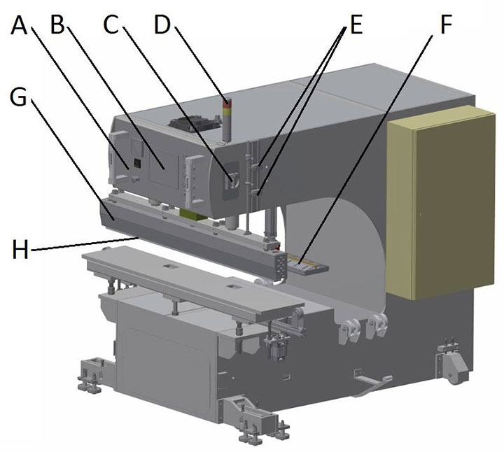
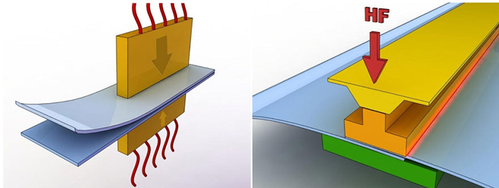
Welding head (without the bench) – basic elements of the machine:
A – handling and control elements placed on the control panel;
B –HMI touch-panel; C – main switch;
D – signalling column;
E – limit switches indicating the electrode position; F – grounding electrode;
G – electrode holder;
5.1 Information and Signs of Restrictions and Imperatives
The Manufacturer provides appropriate packaging of the machine for the time of transportation. Packaging type and durability are adapted to the distance and the means of transport, and consequently to the potential risk of damages during transportation. The Manufacturer suggests that every Client uses the means of transport and technical service personnel of the Manufacturer.
Storage of the machine does not involve any particular requirements, apart from appropriate storage environment.
The storage room must ensure sufficient protection against weather factors, it should be as dry as possible and have an acceptable level of humidity (below 70%). It is also necessary to ensure appropriate protection against corrosion, particularly regarding metal components that are not painted for technical reasons.
If the machine is supplied in a box and is wrapped in plastic generating anti-corrosion atmosphere, the machine should stay wrapped and packed for the entire storage period.
For the purposes of protection against humidity, it is recommended that the machine is not stored directly on the floor of the storage room, but rather on pallets.
A component that requires special attention and handling at every stage – including storage – is the generator lamp (triode). The lamp must be stored in its original packaging, in vertical position, with anode directed to the top or bottom, in a dry room. The lamp is a high-vacuum, metal and ceramic component, which is extremely fragile and cannot be hit or dropped even from low height.
Hitting, dropping, shaking or tilting the lamp for a longer time may and usually do result in permanent and irreversible damaging of the lamp. In particular, the filament of the lamp - cathode can be broken, which in most extreme cases can lead to internal short circuits or lamp breaking.
ATTENTION: Manufacturer suggest not to employ any pregnant or nursing woman in the zone of active non-ionic radiation.
The above provisions are meant to instruct and warn all persons and services that may have contact with this unit concerning its high vulnerability to all impulses and strokes. At the same time, no claims connected with permanent damages described above will be accepted in the course of the complaint procedure.
It should also be emphasized that the generator lamp is a very expensive component.
In the case of any doubts, it is recommended to consult the specialized staff of the Manufacturer.
5.2 Transportation of the machine
The party responsible for the transportation and installation of the machine in the Site of the Ordering Party should be determined at the stage of signing the contract and not later than after the final acceptance test of the machine in the Site of the Manufacturer, before the device is handed over to the Ordering Party.
ATTENTION: Careless handling of the device during transportation / moving may result in serious injuries or accidents.
IT IS FORBIDDEN to assembly, dismantle or transport the machine by personnel without proper qualifications or without being acquainted with safety requirements described in hereby Operation and Maintenance Manual. Such actions may cause accidents or material damage.
Taking into account the specific character of the device, the Manufacturer suggests that every Ordering Party uses the means of transport and technical service personnel of the Manufacturer.
The power tube must be disassembled before any transportation or moving actions.
The lamp must be always transported or moved in the original manufacturer’s packaging, in vertical position, with anode directed to the top or bottom, without any hitting or shaking the lamp.
ATTENTION: The machine should be transported in vertical position.
Due to its size and structure, the machine requires disassembly and disconnection of some components and units for the time of transportation or moving. It is necessary to disassemble fragile and expensive components and tools (which should be transported in a separate case). It is absolutely necessary to dismount the generator lamp.
The machine should be moved using lifting devices – cranes, fork-lift trucks, pallet trucks – with sufficient lifting capacity enabling safe transportation of the generator, whereas the people operating such lifting devices should have all valid licenses and qualifications required by law.
All components of the machine that might be damaged during transportation (if a packaging box of high durability is not used) or by lifting or moving devices should be appropriately secured (provided that they are disassembled and packed separately).
In order to ensure stable position of the device, it is very important to ensure appropriate protection of the machine for the time of long transportation (safety belts, anchor bolts), as well as protection and assistance during in-site transportation.
If the machine is not equipped with appropriate fittings, it is possible to use any other available holes or elements of sufficient durability can be used to ensure that the generator and other parts of the machine are properly balanced and stabilized.
Weight of the machine (about 1100 kg) must be definitely taken into account while planning the transportation.
5.3 Installation In The Place of Operation
Depending on the degree of complexity of the machine, the installation in the place of operation should be performed by the personnel of the Ordering Party, having read this Operation & Maintenance Manual or technical service staff of the Manufacturer, in cooperation with the personnel of the Ordering Party.
Please remember that appropriate positioning and installation of the welding machine is vital for ensuring its optimum functioning, as well as the comfort and safety of the operator in the device’s environment.
The Ordering Party is responsible for preparing the place for the installation of the device, availability and preparation of electrical connections and realization of the particular requirements of the technical design and technical acceptance tests approving the entire generator for use.
The Manufacturer will provide the Ordering Party with all the required instructions and information in this respect.
ATTENTION: Make sure that the floor / surface / foundations on which the machine is to placed have sufficient durability, taking into account the weight, surface and distribution of the machine weight to its points of support (usually legs).
ATTENTION: The device must be properly leveled and must have fixed place of a operation.
Optimum place of operation of the HF welding machine is the concrete surface not covered or covered with a very thin layer of non-conducting material.
The surface should be made in accordance with the particular design following construction and safety standards, as well as following the requirements concerning parallel, perpendicular and flat positions.
ATTENTION: The Ordering Party is solely responsible for the realization of the aforementioned conditions.
After the location of the welding machine in the selected place, it is necessary to level the machine, check its technical condition and remove any and all defects that might have occurred during transportation. Next, unpack, position, level and fix the generator. The high-frequency generator lamp should be mounted in the very end of the installation process. This task must be done with particular attention, both when mounting the lamp in the socket/base and when connecting the lamp’s electrical contacts. Connect the connectors of the control console to appropriately marked sockets on the press. It is recommended that the installation of the machine after transportation is performed under direct supervision of a representative of the manufacturer.
ATTENTION: If the aforementioned tasks are performed by a representative of the Client, they should be performed strictly in accordance with the description contained in this Operation & Maintenance Manual and / or instructions provided by the manufacturer during the technical acceptance test.
Due to the generated magnetic field, large metal items should not be placed near the machine. The machine can affect the operation of electronic devices (radio, TV sets, computers) located near the machine, as a result of high input sensitivity of the aforementioned devices. Optimum place of operation of the machine is the concrete surface not covered or covered with a very thin layer of non-conducting material.
5.4 Installation In The Place of Operation
5.4.1 General Information
ATTENTION: The Manufacturer strongly recommends to install the machine only in industrial environment.
The machine being the subject of this Operation & Maintenance Manual has been designed and manufactured for the purposes of work in the industrial environment for processing conveyor belts.
Specific conditions of operation of the devices, i.e. high air humidity, high temperature, steam and dust, have been taken into account by the designers of the machine and do not affect its operation, but determine more stringent requirements concerning the performance of preventive programmes.
The machine cannot be used in potentially explosive atmosphere, highly dusted atmosphere, environment with high humidity and / or high temperature and the presence of aggressive fumes (acidic, basic, organic or inorganic, having potentially or factually corrosive impact).
The temperature of the work environment should range between +10º C and +40º C and the relative humidity: between 30% and 90%. Condensation of atmospheric moisture or any aggressive substances on the surface of the machine (or any of its components) is not allowable.
It is required that the long-term temperature amplitude during the day in the generator operation room do not exceed 10º C and in the case of relative humidity: 10%.
The clause above does not apply to the media or substances used for greasing, preservation or non-aggressive substances used in the course of production / operation of the device.
ATTENTION: If there is large difference between the outside temperature and the temperature in the room where the machine is installed, the device should be started after 24 hours from its assembly in the room.
5.4.2 Lighting
The requirements for the minimum luminous intensity state that on the horizontal operating area, illuminance that can be accepted in rooms where people stay for a longer time, regardless of whether there are any visual activities performed should be 300 lx.
In the case of visual activities whose difficulty level is higher than average and when highly comfortable seeing is required, as well as when the majority of operators are over 40 years old, the required luminous intensity should be higher the minimum, i.e. at least 500 lx.
5.4.3 Noise
The machine does not generate noise of the level that would require using any means or devices of personnel protection.
However, it must be remembered that all work environments have its own noise emissions, which might have impact on the level of noise emitted by the machine during its operation.
5.5 Connection Parameters
5.5.1 Electrical Enegry
Connection: 3 x 480V; 50Hz (3P+N+PE), overcurrent protection with delayed properties. The installation of the Client must ensure electric shock protection measures conforming to EN 60204-1:2001.
ATTENTION: Always check the filament voltage after installation the tube – see tube technical data.
5.5.2 Compressed Air
Pressure: 0.4 – 0.8 MPa, demanded cleanness class according ISO8573-1 4-4-4, consumption: 70 nl per one cycle.
ATTENTION: If the pressure in the End User’s system is higher than 0.8 MPa, it must be reduced to about 0.6 MPa with a reducing valve mounted on the welding machine connection.
5.6 Connection Parameters
Depending on the complexity of the system and the qualifications and licenses of employees, the connection of the welding machine in the place of its operation is performed by people selected by the Ordering Party or technical service workers of the Manufacturer, in cooperation with the personnel of the Ordering Party, for an additional price or free of charge, which is always arranged before the machine is handed over to the Ordering Party from the site of the Manufacturer.
It is always necessary to check whether all connections have been performed in accordance with the documentation of the device.
It must be stated that the aforementioned tasks require appropriate qualifications of the personnel, including applicable licenses issued by the appropriate bodies.
It applies both to specialised qualifications, as well as completed and valid training courses in Occupational Health & Safety, including particularly the risks involved in those tasks.
6.0 Operation
6.1 Preparation of the Machine for Operation - First Start Up
ATTENTION: In order to use the machine in an optimum and safe way, please read carefully and follow all the instructions included in this Operation & Maintenance Manual.
IT IS FORBIDDEN to execute any work at the welding machine by people without being previously trained in high frequency machines service and Industrial Safety regulations with the special consideration of possible risk coming from the machine.
Provided that all the installation requirements have been met and the tasks described in Item 5 have been performed, we are ready to start the welding machine for the first time in the production environment of the site of the Ordering Party.
ATTENTION: The first start-up of the machine should be performed in the presence and under supervision of the representatives of the Manufacturer.
6.2 Operating Requirements - General Instructions and Guidelines
All adjustments and calibration required for the correct device operation parameters have been done by the Manufacturer during the assembly and internal test procedures. General conformity with contractual technical requirements and correct operation of the machine are confirmed during the technical acceptance taking place in the site of the Manufacturer, in the presence of a representative of the Ordering Party and using original raw materials delivered by the Ordering Party for the testing purposes.
ATTENTION: Due to the specific properties of the devices that emit high-frequency energy, it is necessary to carry out certain measurements in the place of the device’s operation in the site of the Ordering Party. For the same reason, it is very important that the machine has a fixed place of operation.
BEFORE OPERATION IS ABSOLUTELY NECESSARY TO CONTROL:
- Effectiveness of electric shock protection measures;
- Power supply voltage – value and correctness of phases connection;
- Direction of engine rotation (if applicable);
- Incandescent filament lamp voltage;
ATTENTION: The lamp voltage must be the same as specified in the datasheet of the product – it is possible to adjust it using branches on the primary side of the incandescent transformer.
ATTENTION: Due to the specific character of the device, it is always necessary to warn and inform the personnel about high power supply voltage of the lamp’s anode and the potential risk of fatal electric shock by electric current of the voltage of up to 8000 VDC.
ATTENTION: The lamp must be preheated for about an hour after the installation.
- Position of the holder to the base of the working table;
- Emission of electromagnetic field – after the adjustment of welding parameters, during the welding process;
ATTENTION: High frequency welding machine is the source of non–ionic electromagnetic radiation. After installation of machine at buyer's place, non-ionic radiation measurement must be done. The radiation measurements should be done by authorized company.
ATTENTION: Machine must work in a firm working place as transposition requires new measurement of non-ionic radiation intensity.
ATTENTION: It is forbidden for people with implanted pacemaker to stay in the zone of active non-ionic radiation.
ATTENTION: The Manufacturer suggest not to employ any pregnant or nursing woman in the zone of active non-ionic radiation.
IMPORTANT: If the high-voltage circuits have been accidentally connected when the anode is disconnected or the generator lamp is defective, the high-voltage filter condensers must be discharged by short-circuiting them with the casing for a very short time.
ATTENTION: All activities during the start-up and measurements, when the safety level is lower (open protection screens, blocked key switches), must take as little time as possible, and the full machine operation safety level must be ensured as quickly as possible.
ATTENTION: All control & measurement activities must be performed after checking whether the switches for anodic voltage adjustment are in 0 – OFF position (it does not apply to measurement of the emission of electromagnetic field).
ATTENTION: All control & measurement activities must be performed exclusively by authorised personnel.
IT IS ALWAYS PROHIBITED to start the welding process, i.e. turn on the high voltage of the lamp, which initiates the high-frequency voltage on the insulated holder of the electrode, when the safety level of the device operation is reduced.
The machine is adapted to work in the automatic cycle. Automatic mode is the standard mode of operation of the device during the production process.
The high frequency welding machine enables the operation in the manual mode for adjustment purposes.
Machine operators should always wear standard work clothes and anti-slip footwear.
The working environment of the device, the floor and the manual holders and grips must be always clean and free of any contamination, grease or mud, in order to reduce the risk of slipping or falling to the minimum possible level.
Never use the machine of operation without the fixed or mobile protection elements. Check regularly whether all protection screens and all other protection elements are properly mounted and function properly.
Only authorized persons, who are properly trained in the machine operation and Occupational Health & Safety, can have direct contact with the machine.
Each operator of the device must be instructed on the functions of the protection elements of the machine and their proper use.
In the area surrounding the device (about 1.5 m around the generator and press), there can be no items that might interfere with the operation of the device. This area must be kept clean and have proper lighting.
Never use the machine’s manipulators or flexible pipes as holders. Please remember that any accidental moving of the device’s manipulator can accidentally start the welding process, change parameters or even cause the failure of the machine or damage its tools.
IT IS OBLIGED to inform the supervisor and / or traffic personnel about any and all cases of incorrect operation of the device.
6.3 Controls and Indicators Available For Operator
All welder’s controls and indicators can be easily found either on its construction or on its control desk. Before getting down to work, the machine operator should acquaint themselves with the arrangement of the controls and indicators on the machine as long as with the functions they control.
The complete list of the above mentioned controls and indicators available for the operator is attached below:
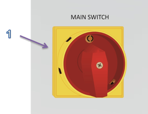
- MAIN SWITCH - a switch (Fig.3) designed for switching on or off the electricity supplies. 1-ON position means that the switch is switched on whereas the 0-OFF position means that the switch is switched off.
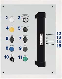
Fig.5. The arrangement of the controls and indicators on the control panel I: 2 – POWER; 3 – TWO-HAND CONTROL OFF/ON; 4 – HF; 5 – HF OFF/ON; 6 – USB; 7 – ETHERNET; 8 – RESTART; 9 – STOP; 10 – JOISTIC; 11 – START; 12 – electrode up; 13 – turn left; 14 – turn right; 14 – electrode down.
-
POWER – an indicator, which flashes white when the machine is connected to the power supply (Fig.5).
-
TWO-HAND CONTROL OFF / ON – a key switch (Fig.5) for the activation of the machine control mode for two hands. The switch refers to the push-buttons located on the black handles and the electrode for raising and lowering functions in the joystick. The switch in the ON position - means that in order to activate the push-buttons, both push-buttons for the same function should be pressed whereupon the joystick loses its electrode raising and lowering function. The switch in the OFF position indicates the possibility of controlling by means of a single push-button and that the electrode is raised and lowered by means of the joystick.
 ATTENTION..! Switching off the two-handed control mode makes the work operations easier; however it significantly increases accident risk. Only an authorised and correctly trained, responsible person should have the key for the on/off switch.
 -
HF - when the indicator flashes yellow it means that the HF welding process is on (Fig.5).
- HF OFF/ON – a switch with the help of which the HF current can be released or put on hold (when it is in OFF position it means that the HF weld cannot be performed)
 As long as the standard welding procedure is concerned the HF OFF/ON switch should be in ON position.When the HF OFF/ON switch is turned to OFF position it means that the duty cycle can be performed without releasing the HF current.
 -
USB slot – a slot (Fig.5) into which a USB memory card for the storage of welding parameters and the history of messages may be inserted; this also allows the saving of the recipes stored in the HMI panel.
-
ETHERNET slot – a slot (Fig.5) into which the Ethernet cable is connected when machine diagnosis is required online allowing internet access to the machine.
-
RESTART – the blue push-button (Fig.5), which should be used to restart the machine control and protection system whenever the alarm message is displayed on the HMI panel.
-
STOP – the black push-button (Fig.5) is designed for switching off the process of high frequency welding.
-
JOYSTIC - joystick (Fig.5, Fig. 7) used for the move forward and backwards head of the welding electrode as well as machine driving to the left or to the right with a slow start for easy positioning. With joystick however you can lower or raise the electrode only when the two-hand mode is activated. There are two travel speed:
• "slow” – (Fig. 6 – A, C, E, G) speed move determined by the parameter located in Service menu panel HMI - Drive speed MANUAL – SLOW.
• "fast” – (Fig. 6 – B, D) speed move determined by the parameter located Service menu panel HMI - Drive speed MANUAL – FAST.
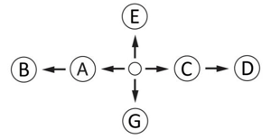
Fig. 6. Positions joystick:
A – slow move of the head to the left, B – fast move of the head to the left,
C – slow move of the head to the right,
D – fast move of the head to the right,
E – electrode up,
F – electrode down,
-
START – the green push-button (Fig.5) is used for switching on the process of high frequency welding.
-
 up arrow – two push-buttons on the black handles on the operator’s panel (Fig. 5, Fig. 7) used for activating the electrode into upper position. When the two-hand operation mode is activated, both push-buttons should be pressed simultaneously
 -
 left arrow - two push-buttons on the black handles on the operator’s panel (Fig. 5, Fig. 7) allowing the machine to move left. When the two- hand operation mode is activated, both push-buttons should be pressed simultaneously.
 -
 right arrow - two push-buttons on the black handles on the operator’s panel (Fig. 5, Fig. 7) required allowing the machine to move right. When the two-hand operation mode is activated, both push-buttons should be pressed simultaneously.
 -
 down arrow – two push-buttons on the black handles on the operator’s panel (Fig. 5, Fig. 7) used for activating the electrode into lower position. When the two-hand operation mode is activated, both push-button must be presses at the same time.
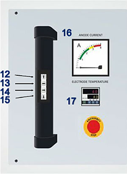
Fig. 7. The arrangement of the controls and indicators an the control panel:
12 – electrode up;
13. turn left; 14. turn right;
14. electrode down
15. ANODE CURRENT;
16. ELECTRODE TEMPERATURE;
17. EMERGENCY STOP;
-
ANODE CURRENT - the panel ammeter (Fig.5) is supposed to indicate the value of current intensity in La anode circuit and should enable the operator to conduct the vision inspection of the welding process (The Generator Full-load Characteristics).
-
ELECTRODE TEMPERATURE - a thermo-regulator (Fig.6) used for the adjustment of the electrode's temperature. This controls the system which stabilizes the electrode's temperature. A push-button, Temp Regulation in the Main screen window of the touch-panel is used to activate the temperature stabilization feature. The owner’s manual referring to the E5CC temperature can be found in the attachment.
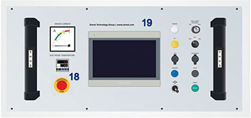
Fig. 8 Control panel;
18.– EMERGENCY STOP;
19. - HMI; - EMERGENCY STOP - the red mushroom-headed push-button (Fig.5) it is a button that should be pressed only when the functions of the machine need to be halted immediately or when anything regarding the machine’s functions or the operator’s surroundings pose a threat to the production or safety.
 The EMERGENCY STOP button should not be overused, it is supposed to be used only in case of emergency.
 -
HMI PANEL – the touch-sensitive panel (Fig.5) should be used for changing the machine’s setting parameters and it is supposed to become a reliable source of information about the current state of the welding machine. See chapter 6.6. for more information about performing the servicing procedure applying to the touch-sensitive panel.
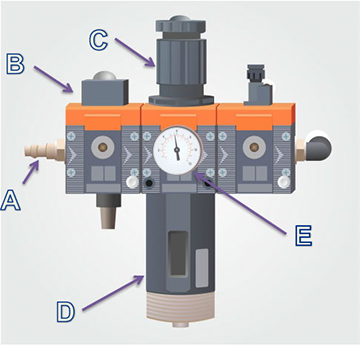
Fig.9. THE COMPRESSED AIR PREPARATION SYSTEM.
-
COMPRESSED AIR PREPARATION SYSTEM (Fig.9) – consists of:
A. The compressed air terminal into which the compressed air hose should be connected. The hose is supposed to provide the system with the compressed air ranging from 0.4 to 0.8 MPa;
B. The manually operated compressed air shut-off valve (in order to open the valve - turn it to the left and set to ON position; a turn to the right - the OFF position - the valve is closed);
C. The compressed air terminal into which the compressed air hose should be connected. The hose is supposed to provide the system with the compressed air ranging from 0.4 to 0.8 MPa; 0.6 M
 The level of pressure in the pneumatic system never exceeds the level of pressure propelling the machine.
D. The compressed air filter along with the condensation water release mechanism;
E. The manometer indicating the level of pressure in the machine’s compressed air system;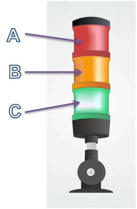
Fig.10. The signal light column:
A - red color;
B - orange color;
C - green color
21. SIGNAL LIGHT COLUMN (Fig.10):
A. Red color indicates failure and at the same time the alarm message should be displayed on the HMI touch-sensitive panel.
 The alarm massages are deleted and the red light on the signal light column stops flashing when the RESTART button is pressed.
In case the efforts were put in vain and the alarm message has not been deleted when the RESTART button had been pushed so it might mean that the cause of failure occurrence had not been removed yet.
See chapter 6.6.2. for further information applying to the alarm massages.
B. Orange color indicates that the high frequency welder starts operating.
C. Green color indicates that the machine is ready for work.
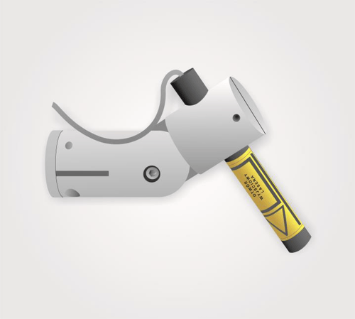
Fig. 11. One of the laser indicators placed on the right side of the welding head.
22. Lasers installed on the welding head (Fig. 11) used for the projection of the welding line on the welded/sealed material. Useful for placing and positioning the material along the welding line. They are switched on directly from the HMI touch-panel.
|
|
|
 ATTENTION..!
The laser is to mark the line ON the MATERIAL in the position of the electrode and its holder up. The laser DOES NOT / MUST NOT shine on the front or back edge of the electrode in its position on the material / lower.
Laser regulation procedure:
1. Put the material on the table and lower the holder with the electrode on the table,
2. Use a marker pen to draw a line outlining the front and possibly the rear edge of the electrode (if two lasers are mounted on one side),
3. Lift the electrode up and set the laser / lasers to the drawn lines, possibly with such an offset from these lines as the operator wants to position the foil,
4. Be careful that the material does not move.
|
|
|
 The laser handles and the lasers themselves, if they are located in
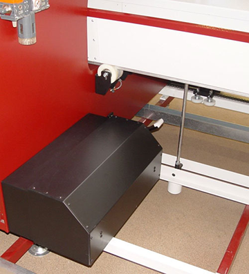
Fig. 12 The bumper
23. The side bumpers installed on both sides of the welding head (Fig.9), prevent the machine from colliding with anyone or anything. Any jolt on a bumper will result in the instant disconnection of the machine’s propulsion system; this will be indicated by the message: OPEN GUARD/ EMERGENCY BRAKE.

Fig. 13 Emergency move
23. Emergency move – the switch is used to change the operating mode. In case of an obstacle and stopping on it. The switch deactivates the side bumpers and allows the exit from an obstacle. After switching the switch to position I on the HMI, the "emergency trips" window appears in which the user has the option of using the navigation arrows to pass the welding head left or right at the slow speed. Switching the switch to position 0 activates the side bumpers and restores the correct machine operation mode.
|
|
|
 Operation ATTENTION! As the aforesaid system needs to work flawlessly it is strongly recommended to perform the adjustment of the height limiter in such a way that it should indicate the lower position of the electrode. Inappropriate setting of the height control slide of the limit switch may result in both a self-triggered emergency lifting of the electrode and the appearance of the following alarm message on the HMI display: EMERGENCY ELECTRODE UP.
Limit switches for the height of the electrode:
- upper limit switch – when switched on (Fig. 14-A) indicates the upper electrode position. Adjustment of the slider, which activates the switch, must be done when the maximum upper position of the electrode has to be changed. If the limit switch is moved too high, it will not switch on in the upper electrode position – the welding cycle will not be finished and the machine's drive cycle will not be possible. If on the other hand, it is too low – the electrode will not be raised to a sufficient height after the weld cycle and can catch the welded material during its drive, causing damage.
- Lower limit switch – when switched off (Fig. 14-B) indicates the lower electrode position above the work table. Adjustment of the slide on this switch should be carried out each time the electrode has been replaced (when the new electrode is of a height different to the previous one) and when there is a significant change in the thickness of the welded material. The lower limit switch is also an element of the system which protects the operator’s hands from being crushed. If its adjustment is not carried out properly, the anti-crush (ZTG Anti-CRUSH) protection feature will be activated causing the automatic lifting of the electrode into its upper position. The limit switch must be placed at a height that will cause the switch’s rolling wheel to be pressed in by the lower slider of the electrode's height located on the rod from the moment the electrode touches the welded material. (Fig. 14- B).
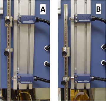
Fig. 14 Limit switches indicating the electrode's position:
A – upper position;
B – lower position.
Adjustment procedure and determining the correct height of the lower limit switch:
- place the material to be welded on the work table,
- put the electrode into the tool holder and lock it,
- lower the electrode holder with the electrode onto the material, so that the electrode just touches it without any pressure (leave a gap of maximum 5mm / 1/8inch); leave in this position.
- move the lower metal slider on the rod to the position that will disconnect the lower limit switch (the switch roller is directly on the slider (Fig. 14- B),
- if it is not possible to set the metal slider at an appropriate height due to its step adjustment (every 15 mm), loosen the two screws holding the limit switch and move it into a lock-in position with the roller to the lower metal slider of the electrode height (Fig. 14- B), then tighten the screws.
- raise the handle with the electrode into its upper position,
- if it is not possible to set the indicator at an appropriate height due to its step adjustment (every 15 mm), loosen the two screws fixing the switch and move it into such a position that will move its roller to the lower indicator of the electrode height (Fig. 14- B), then tighten the screws.
ATTENTION! Manipulation with the limit switch indicating the lower position of the electrode excluding the one quoted above is strictly forbidden. Disregarding the manufacturer’s warning may lead to the severe machine failure and as a result to serious body injuries.
In addition, the machine has been equipped with an additional electrode, enabling welding without the use of grounding electrode. After installing this kind of electrode in the holder and starting to lower it, an additional limit switch is activated, which inhibits the movement of the grounding electrode.
6.5 Operating Temperature Controller E5CC
Temperature control unit is used to control the temperature of the electrode. Programming the right temperature of the electrode is required to correct the course of the welding process. The temperature should be selected experimental. Below is a description of the display and control panel temperature control unit (Fig. 15).

Fig. 15. Display and control panel thermoregulatory.
- Display with four digit (white) which displayed actual temperature value. In parameter settings mode display present sign of edited parameter.
- Display with four digit (green) which displayed actual ordered temperature value. In parameter setting mode display present actual value of edited parameter.
- Control buttons:
 move button. Pressing this button cause to edit next digit from edited number.
 - button „DOWN” cause low edited digit by one.
 – button „UP” cause increase edited digit by one.
 In the parameter edit window, go to the next parameter
 Long press this button (min 3sec.) cause pass to edition mode of leave parameter. If system work in edition mode, pressing button cause return to the main window
CONTROLLER SETTINGS – ORDERED TEMPERATURE VALUE
To change ordered value need to short press button (Fig. 15) or . It caused pass to parameter edition mode. Available number which will be edit is signalize by quick blinking its. By buttons “UP” or „DOWN” set value of this number, next press „move” button , which move to next position to edition.
6.6 Programming and Operating the HMI Touch-Sensitive Panel
ATTENTION! Each value of the parameter depicted on the graphics of this manual is taken at random and should be disregarded by the machine’s operator. The values of the parameters should derive from user’s practical experience as they may vary profoundly according to the type of welded material or implemented instrumentation.
![]() In the HMI panel all editable values of the parameters are displayed on a white colour background. In order to display a parameter the user needs to press its value and as a result the on-screen keyboard should be opened. Data can be saved by pressing Enter key.
In the HMI panel all editable values of the parameters are displayed on a white colour background. In order to display a parameter the user needs to press its value and as a result the on-screen keyboard should be opened. Data can be saved by pressing Enter key.
6.6.1 Connection to Power Source
Shortly after the machine is connected to a power source on the HMI display an alarm window appears along with the following message:
#A001 EMERGENCY STOP
#K001 PRESS RESTART BUTTON
According to this situation, the machine needs to be restarted so the blue RESTART key should be pressed. Then we need to wait for 30 seconds till the machine is ready for work and enters a stand-by mode which we know due to the following facts: a light indicator in the light signal column flashes green and the progress bar displayed in the HMI main window flashes green. In case the alarm massage does not disappear from the HMI display see chapter 0.
6.6.2 Alarm Messages
When a machine failure occurs or when one of the protection systems is switched on or when some other abnormalities in machine’s functioning are detected then one of the alarm messages is going to be displayed on the HMI touch-sensitive panel. All alarm messages are deleted with the help of the RESTART key.The types of alarm massages:
#A001 EMERGENCY STOP – this kind of message is displayed when:
- the machine is switched on - the machine’s safety circuit must be always checked when the RESTART key is pressed,
- the red mushroom-headed EMERGENCY STOP push-button was pressed and has been jammed. It needs to be unstuck by turning its head to the right.
#A002 TUBE TEMPERATURE – this type of massage means that either the travelling-wave tube cooling does not exist or that the cooling system failure occurs and it is displayed when:
- the fuses that are supposed to protect the power supply circuit of the fan which should cool down the travelling-wave tube are disconnected;
- the contactor that is supposed to trigger the fan that should cool down the tube is either turned off or damaged;
- the tube thermal protection system is put into operation which means that the travelling-wave tube got heated up to too high temperature and as a result the tube band cotter pin that had been connected to the limit switch by a cord got unsoldered.
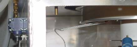
Fig.16. The tube thermal protection system.
A cotter pin is soldered to a tube band with the help of a solder of melting point much lower than the one at which the tube got overheated (got damaged). If the lamp temperature rises too much the cotter pin will fall out of the band and as a result the limit switch will be triggered, simultaneously the alarm message will be displayed and the power supply for a glow in the tube will be cut off. Then the cause of overheating should be removed.
ATTENTION! The cord should not be fastened to any other parts of the machine but the cotter pin of the band which had been screwed to the tube. Disregarding the quoted warning can result in a limit switch blockage which may lead to the travelling-wave tube overheating and in consequence of such proceeding to its damage.
![]() If the cotter pin gets separated from the band than the band should be taken off from the tube, the pin should be soldered to the band with the standard solder used in electronic engineering (Melting point < 190oC) so as to the repaired part could be reattached to the tube.
If the cotter pin gets separated from the band than the band should be taken off from the tube, the pin should be soldered to the band with the standard solder used in electronic engineering (Melting point < 190oC) so as to the repaired part could be reattached to the tube.
The tube overheating can be caused by:
- the dirt found either in the generator or in the tube radiator;
- the failure of the tube cooling fan or the failure of the fan power supply system;
- the blockage of the machine’s ventilating holes or by the excessive amount of soil collected by the filters installed in the ventilating holes;
- the excessive ambient temperature.
#A003 ANTIFLASH – this type of massage means that the protection system against an arc-over while welding was triggered - due to this message make sure neither the insulating pad, welded material nor the welding electrode had not been damaged.
#A004 ANODE OVERLOAD – this message means that the anode-rise limit was exceeded so the parameters applying to the power released in weld need to be adjusted.
#A005 GRID OVERLOAD – this message means that the grid-rise limit was exceeded so the parameters applying to the power released in weld need to be adjusted.
#A006 LOW AIR PRESSURE – this message means that there is lack of air pressure or the level of air pressure is too low in the pneumatic system. Make sure the hose providing the compressed air is connected to the machine or the level of compressed air is appropriate and then with the help of pressure reducing valve regulator which can be found in the compressed air preparation system adjust the pressure in the machine to the adequate level.
#A008 ELECTRODE IS NOT IN UPPER POSITION –. the message will be displayed if the welding electrode is not in the upper position after switching on the machine. Check the tightness of the pneumatic system and the correct setting of the limit switch indicating the upper position.
#A011 ELECTRODE TEMPERATURE – this message signals that the set point electrode temperature on the thermoregulator has been exceeded – the machine will be disabled into emergency mode. You should wait until the electrode cools and then check whether the temperature setting on the temperature controller is too high. Another possible option is that the electrode's warm up circuit has broken down. The manufacturer’s service should be contacted in such a case.
#A013 WELDING PARAMETERS NOT REACHED – the machine's control software includes an algorithm which checks whether each partial weld has been properly carried out. If, during the welding, the parameters set out have not been achieved or if welding has been stopped before the task has been completed, the above message will be displayed. The quality of the weld will then be checked and if unsatisfactory, the task must be repeated.
#A019 SENSOR / DRIVE ERROR - ELECTRODE DOWN - the alarm message will be displayed when, after actuating the valve coil, the controller will not receive confirmation from the sensor confirming the achievement of the lower position within 15 seconds. Check whether the sensor has not moved or check that the pneumatic system is close to the actuator.
#A020 SENSOR / DRIVE ERROR - ELECTRODE UP - the alarm message will be displayed when, after actuating the valve coil, the controller will not receive confirmation from the sensor confirming the achievement of the upper position within 15 seconds. Check whether the sensor has not moved or check that the pneumatic system is close to the actuator.
#A032 START CAPACITOR POSITION NOT ACHIVED – the message will be displayed if the capacitors do not reach the preset position within 15 seconds. Check the capacitor drive.
#A034 EMERGENCY ELECTRODE UP – this message is displayed when the electrode holder which was being lowered upon the work table encountered an obstacle on its way and the protection system against squeezing hazard was put into practice. Make sure there is not anything between the electrode and the work table. If the alarm message does not disappear the adjustment of the switch limit indicating the lower electrode position needs to be conducted. See chapter 6.4. for more information applying to the switch limit adjustment procedure.
#A035 CHECK RESET CIRCUIT IN SAFETY RELAY – means that the safety circuit of the machine has probably been damaged. The manufacturer’s service should be contacted in such a case.
#A046 CURRENT NOT IN TOLERANCE DURING WELDING - this message will be displayed if the current value cannot be reached during operations. The algorithm checks if the anode current has been met. The anode current obtained must be within +/- of the tolerance range of the anode current value for a given percentage of the time for the duration of the welding, specified in the Service Window after choosing Welding process control option.
#A047 DOWN FORCE NOT IN TOLERANCE DURING THE WELDING -this message will be displayed if, during welding, the current downforce falls outside the tolerance range specified in the Service Window after choosing Welding process control option.
#A053 EMERGENCY BRAKE – This message is displayed when the safety switch is pressed. When the mushroom switch is activated in an emergency, the head will suddenly - and violently - brake.
#A054 SAFETY VALVE DAMAGE – This message is displayed when the sensor (marked with the symbol 10B1 on the electric diagram) of confirmation piston valve in the appropriate position is activated. This sensor is located on the safety valve (marked with the symbol 1V3 on the electric diagram). If the piston of safety valve does not reach the correct position, it means that the valve is not working properly.
#A055 SERVO ALARM – this signals an error in the Y-axis drive. Restart the machine and, if the message does not disappear, check the alarm number displayed on the servo and check the description in the servo-drive directory.
#A056 LOW AIR PRESSURE IN SUPPORTING CYLINDERS – means that air pressure in the servomotors supporting the electrode is too low which can result in a rapid lowering of the electrode and it hitting the bench. Adjustment of the compressed air pressure in the circuit of these servomotors should be carried out.
#A057 WELDING POSITION NOT REACHED - the alarm message will be displayed when, after controlling the valve coil, the controller will not receive confirmation from the sensor confirming the achievement of the set position within 8 seconds. Check whether the sensor has not moved or check the tightness of the pneumatic system at the actuator.
#A058 THE ELECTRODE IS NOT LOCATED IN A LOWER POSITION – the alarm message will be displayed if the START button is pressed and the electrode is not in the down position. Lower the welding electrode onto the material.
#A059 TABLE - ERROR OF SET DRIVE POSITION – The alarm message will be displayed if the controller does not receive confirmation from the sensor that the desired position has been reached within 8 seconds of the valve coil having been actuated. Check that the sensor is in position and also check the air tightness of the actuator.
#A060 EMERGENCY REBOUND - AXIS X START/END – The alarm message #A061 X-AXIS BASING ERROR is displayed, together with the alarm, when the end switch, located on the head, is activated. At that moment, the head will deflect and the system will blow.
#A061 AXIS X HOMING ERROR – The message is displayed when the end switch, located on the head, is activated. This may be due to the operator having entered an incorrect, table length value- i.e. one higher than the actual length- in the Movements settings in the service menu . A basing error may also occur in the case of an active endpoint after basing.
#A062 SET PRESSURE HAS NOT BEEN ACHIEVED – The message will be displayed if the specified value of the pressure parameter is lower than the lower tolerance range, specified in the service window in the control parameters of the welding process.
#A063 EMERGENCY REBOUND - AXIS Y START/END - The alarm message #A061 Y-AXIS BASING ERROR is displayed, together with the alarm, when the end switch, located on the head, is activated. At that moment, the head will deflect and the system will blow.
#A064 AXIS Y HOMING ERROR – The message is displayed when the end switch, located on the head, is activated.. This may be due to the operator having entered an incorrect “Axis Y up limit” value- i.e. one higher than the actual value- in the Movements settings in the service menu. A basing error may also occur in the case of an active endpoint after basing.
#A075 DRIVE ERROR – the alarm message will be displayed when an alarm occurs on the inverter. If the alarm can not be delete, check the alarm number displayed on the inverter display and check its explanation in the technical documentation of the manufacturer.
#A076 OPEN GUARD - is displayed when one of the shields was taken off - the shields are equipped with the key- switches that turn themselves on only if the shields are appropriately placed and tightened.
#A077 DRIVE COMMUNICATION ERROR – the alarm will be displayed if there is no communication PLC = Inverter. Check that the cable connectors are not removed.
#A080 INCORRECT LENGTH OF WELDING – an alarm message will be displayed if the weld is impossible to make, because the length of the weld is greater than the length of the table it means if the operator wants to start the cycle in BA drive mode but entered the weld length for AB mode. Check:
- the head is at the beginning of the table, or at the end depending on the choice of the AB-BA drive mode,
- passing parameters have been entered correctly in the HF HEAD DRIVE window,
- the actual table length is correctly entered in the SERVICE MENU window.
#A102 LEFT BUMPER – COLLISION - the message is displayed when the left side bumper is activate. In case of stopping in an obstacle (bumper active), turn the EMERGENCY MOVE switch deactivate the emergency system and use the HMI to move the head exit the obstacle.
#A103 RIGHT BUMPER – COLLISION - the message is displayed when the right side bumper is activate. In case of stopping in an obstacle (bumper active), turn the EMERGENCY MOVE switch deactivate the emergency system and use the HMI to move the head exit the obstacle.
6.6.3 Alarm Screen - Emergency Move
The EMERGENCY MOVE window is displayed when the emergency switch is switched to position I (Fig. 13 Emergency move). In the window, the operator has the option of passing the welding head right or left at slow speed. The movement of the head is done by means of navigation arrows indicating the direction of travel.
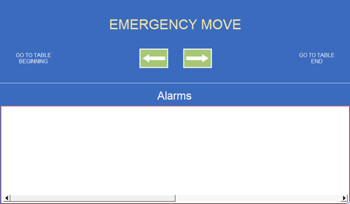
Fig. 17 Emergency move
 Operation on the machine is only possible when the EMERGENCY MOVE switch is in position 0.
Menu can be found in the upper part of the HMI touch-sensitive display panel with the help of which the User can choose one out of five main virtual windows such as:
- Main screen
- Recipes database
- Power setting
- Work graph
- Service menu
6.6.5 Main Screen
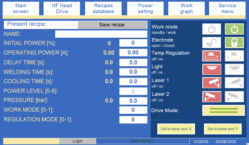
Fig.12. Main screen.
Recipe - under this name a group of parameters applying to the duty cycle can be found. Once the welding parameters for the particular kind of product deriving from practical experience (the parameters’ values strongly depend on the size of weld, the size of welded material and the electrode’s shape) are established they should be entered in the system and saved under the recipe’s name.
 ATTENTION! It is important to remember that in spite of the fact that the above mentioned parameters can be saved under the recipe’s name in the HMI touch-sensitive panel there is also another parameter - ELECTRODE TEMPERATURE that should be adjusted manually.
![]() Additionally, two values next to each parameter’s name can be also found on the HMI display. The first one (on the blue background) is the value of present operating parameter displayed in the actual time, the second one (on the white background) is the set value coming from the production recipe or the operator’s data.
Additionally, two values next to each parameter’s name can be also found on the HMI display. The first one (on the blue background) is the value of present operating parameter displayed in the actual time, the second one (on the white background) is the set value coming from the production recipe or the operator’s data.
![]() Should the need arise, the operator can always press the digit on the white background and change its value. The value of present operating parameter will be updated at once, though, the change does not affect the executed recipe.
Should the need arise, the operator can always press the digit on the white background and change its value. The value of present operating parameter will be updated at once, though, the change does not affect the executed recipe.
![]() In order to save those changes to a recipe which were made using the Main screen, press the SAVE RECIPE button to copy the parameters from the main screen to the Edit recipe bar in the Recipe database window. The parameters copied may be saved as a new recipe using the Create new button or they can be used to update an existing recipe using the Update button.
In order to save those changes to a recipe which were made using the Main screen, press the SAVE RECIPE button to copy the parameters from the main screen to the Edit recipe bar in the Recipe database window. The parameters copied may be saved as a new recipe using the Create new button or they can be used to update an existing recipe using the Update button.
The red sign on the HMI panel in the main window Fig. 19 indicates that the machine is not ready for operation. The buttons on the HMI panel and on the operator panel are inactive until the operator reboots the machine with the blue RESTART button on the operator panel. Selecting the RESTART button has the same effect as attaching the safety circuit and starting the sub-up process of the generation lamp for 30 seconds. During this time, the progress bar gradually turns green (Fig. 20), and the buttons allow the head to pass on the X and Y axes while the buttons allowing the head to drop over the workbench are active; however, it is not possible to switch to high frequency. Once the progress bar is completely green, a READY sign will appear on the progress bar and from that point, all buttons, including the high frequency, activation buttons, will be active.

Fig. 19 Information NOT READY displayed on HMI panel

Fig. 20 Progress bar gradually filling in green after selecting RESTART button on the control panel
Name: - the recipe’s name executed for production purposes.
Initial power – this parameter indicates the position (capacity) of the output capacitor found in the generator; the anode current intensity in the initial phase of high frequency weld strongly depends on the value of this parameter. (Parameter expressed in percentage values, where 0% indicates the lowest level of capacity - the lowest level of anode current intensity and 100% indicates the highest level of capacity - the highest level of anode current intensity.)
![]() The parameter’s value of Initial power and the value of anode current (power released in material) are not linearly dependent as a result the appropriate precautionary measures should be taken when adjusting values of this parameter.
The parameter’s value of Initial power and the value of anode current (power released in material) are not linearly dependent as a result the appropriate precautionary measures should be taken when adjusting values of this parameter.
![]() The current value of Initial power parameter and the value of set parameter are equal to each other only in the initial phase of the welding procedure. When the procedure is initiated, the output capacitor’s position is automatically adjusted in order to achieve Operating power.
The current value of Initial power parameter and the value of set parameter are equal to each other only in the initial phase of the welding procedure. When the procedure is initiated, the output capacitor’s position is automatically adjusted in order to achieve Operating power.
Operating power [A] – this parameter indicates Ia anode current used for welding. (Parameter expressed in ampere values ranging from 0 to 4 A.)
![]() Values in green color on the Anode current meter’s scale indicate the acceptable values of the Ia anode current.
Values in green color on the Anode current meter’s scale indicate the acceptable values of the Ia anode current.
![]() When the welding procedure is initiated the output capacitor (Initial power) is automatically adjusted so as to achieve the Operating power.
When the welding procedure is initiated the output capacitor (Initial power) is automatically adjusted so as to achieve the Operating power.
Delay time [s] – this parameter indicates time during which the electrode had adhered to the welded material before the weld was initiated. (Parameter expressed in second values ranging from 0 to 99 s.)
Welding time [s] – this parameter means time the machine takes to process the high frequency weld. (Parameter expressed in second values ranging from 0 to 99 s.)
Cooling time [s] – this parameter indicates time in which the electrode was being pressed against the welded material after the weld had come to an end - material cools down being pressed against the table. (Parameter expressed in second values ranging from 0 to 99 s .).
Power level [0-6] – is the main setting of the machine's power; adjustment is carried out by changing the anode voltage Ua in the range from 1 to 6 where 1 is low power and 6 is maximum power:
0 - the anode transformer is disconnected;
1 – Ua = 3,4kV;
2 – Ua = 3,95kV;
3 – Ua = 4,75kV;
4 – Ua = 5,87kV;
5 – Ua = 6,85kV;
6 – Ua = 8,2kV;
Pressure [bar] – the parameter indicates compressed air pressure in the pneumatic system of the electrode clamping as expressed in bars; the parameter determines the electrode down-force in relation to the material during welding.
Work mode [0/1] – The parameter defining the welding work mode. 0 value indicates that the machine is working in ‘Time’ welding mode. 1 value indicates that the machine is working in ‘Current’ welding mode. A detailed description of the “Time” and “Current” operating modes is provided on pages 71-72 of the documentation.
Regulation mode [0/1] – The parameter defining the range of automatic adjustment mode of the output capacitor. Typing 1 value (MAX mode) switches it into full automatic adjustment mode of the output capacitor. 0 value (MIN mode) means that during welding, the output capacitor is adjusted only when the anode current exceeds the value inserted in the Power max parameter. A detailed description of the MAX and MIN operating modes is provided on page 72 of the documentation.
Options:
Work mode standby / work
 - green button
  means that the machine is turned on and ready to work, work during normal operations.
 - orange button
  means that the machine is in standby mode. This mode is used to swathing the machine to mode sleep, which gives the possibility to the heating of the electrode before the work shift.
A reference situation:
A working shift lasts from 7:00 am - 3:00 pm.
The Operator ending the shift at 3 p.m. must NOT turn the machine off at the MAIN SWITCH and must NOT press the EMERGENCY STOP button; he/she should only put the machine into STANDBY mode. The STANDBY MODE window then opens (Fig. 21). The operator sets the electrode heating, switch- on time in this window, in the table ‘ELECTRODE FOR HEATING SETTINGS FOR STANDBY MODE’; in our case, heating is to be active from 6:40 to 7:00.
The operator then leaves the machine. This setting will cause the machine’s electrode to engage at 7 each day, as indicated, in order to allow efficient operation from the beginning of the shift and thereby facilitating welding of repeatable qualitny. The above situation is shown in the following graph.
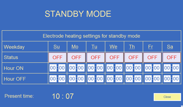
Fig. 21 Standby mode window
|
|
For the standby mode to work properly: It should be switched on in the main window using the orange button
|
|
|
|


 It is possible to disable the STANDBY mode at any time and go
 .
.Electrode open / closed
 - an open padlock on the red background indicates that the welding electrode was not closed in its holder, when you press the grey closed padlock the holder will be closed.
|
|
Additionally, when the message such as ATTENTION, ELECTRODE OPEN flashes, it also means that the electrode holder is open. |
 When
When  - a closed padlock on the green background indicates that the welding electrode is closed in its holder, when you press on the grey open padlock the holder will be open.
|
|
|
|
|
|
 ATTENTION
 ATTENTION! Please pay special attention to the weight of the
Temp Regulation off / on
 - push-button
  signals that the electrode temperature stabiliser is switched on, pressing
  the push-button turns off temperature stabilization.
 - push-button
  signals that the electrode temperature stabilizer is switched on, pressing the push-button turns off temperature stabilization.
 Turning on temperature stabilisation results in the maintaining of a stable temperature level and a repeatable weld quality.
Light off/on
 - a lamp which does not glow on the red background indicates that the work table lighting in the welding zone is switched off, when you press the grey glowing lamp, the lighting will be switched on.
 - a glowing lamp on the green background indicates that the work table lighting in the welding zone is switched on, when you press the grey lamp, the lighting will be switched off.
Laser 1 off / on
 - push-button
  signals that the laser indicator 1 is switched off, pressing the push-button
  turns on the laser indicator 1.
 - push-button
  signals that the laser indicator 1 is switched on, pressing the push-button turns off the laser indicator 1.
Laser 2 off / on
- push-button signals that the laser indicator 2 is switched off, pressing the push-button turns on the laser indicator 2.
- push-button signals that the laser indicator 2 is switched on, pressing the push-button turns off the laser indicator 2.
 In the standard, the laser indicator denoted as Laser 1 is located on the left side of the welding head and Laser 2 on its right side, looking from the front of the machine, that is, from the control panel side / operator's side.
Work Mode
Current / Time
 - the electric circuit on the green background indicates that the machine is working in ‘Current’ welding mode; pressing the grey clock indicates that the machine will enter the ‘Time’ welding mode. ‘Current’ welding mode indicates that the machine’s counter has started counting high frequency weld time, which was entered in the Welding time parameter, as soon as the machine recognizes the appropriate value of the la anode current which should either exceed or be equal to the value entered in the Work current parameter. To put it differently, in Current welding mode, the welding time equals the sum of both the value of the time the machine takes to produce the anode current- that is, the value entered in the Operating power parameter- and the value of time entered in the Welding time parameter.
 If the machine does not manage to produce Operating power within 25 seconds, the duty cycle will be discontinued.
 - the clock on the green background indicates that the machine is working in ‘Time’ welding mode; pressing the grey, electric circuit indicates that the machine will enter ‘Current’ welding mode. The ‘Time’ welding mode indicates that high frequency weld time is equal to the value entered in the recipe’s parameter under the name Welding time.
 It is worth noticing that in ‘Time’, welding mode, the duty cycle can be executed even if the machine has not managed to produce Operating power. The result of this will be that the weld achieved may be of irregular strength.
Regulation Mode min / max
 - push-button
  signals that the machine is working in limited automatic adjustment mode of the output capacitor; pressing the push-button
  switches it into full automatic adjustment mode of the output capacitor. The min mode means that during welding, the output capacitor is adjusted only when the anode current exceeds the value inserted in the Power max parameter.
 - push-button
  that the machine is working in full automatic adjustment mode of the output capacitor; pressing the
  push- button switches it into limited automatic adjustment mode of the capacitor. The max mode means that during welding, the output capacitor is adjusted automatically so that the anode current is at the level set in the Operating power parameter.
Drive Mode – the welding head can work in five passage modes:
 - operation at the site mode – the machine works stationary (welds in the same place without moving). None of the passage parameters are active.
 - working mode from left to right without return – the machine makes a weld at the length set moving to the right and remains at the place of the last weld when the task is completed.
 - working mode from right to left without return – the machine makes a weld at the length set moving to the left and remains at the place of the last weld when the task is completed.
 - working mode from left to right with return – the machine performs welds along the length set moving to the right and returns automatically to the place of the first weld when the task is finished.
 - working mode from right to left with return – the machine performs welds along the length set moving to the left and returns automatically to the place of the first weld when the task is finished.
set to base axis X - the button starts the process of homing the X axis - determining the zero point for the travel of the head. To start, hold down the button. The homing process is indicated by the button blinking. When the button turns green and stop blinking, the process is finished. During the proces homing, the welding head moves to the left until the limit switch operates and bounces off the limit switch by the length set in the program.
set to base axis Y - the button starts the process of homing the Y axis - determining the zero point for the travel of the head. To start, hold down the button. The homing process is indicated by the button blinking. When the button turns green and stop blinking, the process is finished. During the proces homing, the welding head moves to the front until the limit switch operates and goes to the base position ( about the middle of axis).
ALARM MESSAGES STATING: NOT READY TO START WELDING CYCLE:
ATTENTION, ELECTRODE OPEN – signals that the electrode handle is open. Install the welding electrode correctly and close the handle: HMI → Main screen→ Electrode → closed.
NOT READY – signals that the machine did not restart properly and there was no 30-second start-up. Press the RESTART button on the control panel.
If a special electrode has been installed in the holder that enables welding without the use of a grounding electrode, then after pressing the START button on the operator panel, the grounding electrode will remain in the upper position it will not lower. After installing this type of electrode, at the bottom in the main screen of the HMI panel will display the message " WELDING WITHOUT GROUNDING FOOT!"
6.6.6 Recipes Database
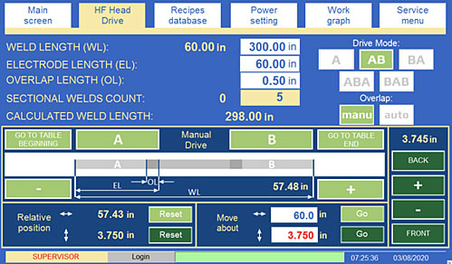
Fig. 22 HF HEAD DRIVE
In the HF Head Drive window there are recipe parameters referring to the head's passage during an automatic welding cycle:
|
|
|
|
|
|
 There
There A partial weld is a welded material surface equal to the surface
|
|
|
|
|
|
 If the entered value is highlighted in red, it means that the welding
 The set values of all parameters in HF Head Drive are examples.
WELD LENGTH – marked as WL denotes the weld length (expressed in inches or centimeters depending on the position of the unit switch in the service menu).
ELECTRODE LENGTH – marked as EL denotes the length of the electrode mounted in the welding (expressed in inches or centimeters depending on the position of the unit switch in the service menu).
OVERLAP LENGTH – marked as OL denotes overlap length. The overlap is the surface area of the material welded where the partial weld overlaps the previous one; this means that the material is welded twice in this place. There are two possible options for the calculations of the overlap chosen by means of the Overlap push-buttons:
 - the optimum length of the overlap and the number of partial welds is calculated automatically on the basis of the total weld length and the welding electrode length (partial weld) input values.
 - the weld length is inserted by the operator. Attention should be paid to input a length that will allow welding of the material along its full length set; otherwise the last weld will need to be performed manually.
SECTIONAL WELDS COUNT – the number of partial welds to be performed by the machine in the automatic cycle to weld the material along its full length set. It is not possible for the operator to set this parameter. It is always calculated automatically on the basis of the total weld length given and the length of the welding electrode.
 If the machine has been stopped during its automatic cycle by pressing the STOP button on the control panel for a minimum of 3 seconds then the cycle will not continue and the number of the partial welds will reset.
 If the machine has been stopped during its automatic cycle by pressing the STOP button on the control panel and the operator moves the joystick then the cycle will not continue and the number of the partial welds will reset.
If the machine has been stopped during its automatic cycle by pressing the STOP button on the control panel and the welding head is in the welding position (regardless of whether the welding process has not started, is running or completed) it’s possible to continue the cycle only if the START button on the control panel will be pressed.
If the machine has been stopped during its automatic cycle by pressing the STOP button on the control panel and the welding head is in the drive position it’s possible to continue the cycle pressing the “Go to the next position” button in the HF head drive window.
Drive Mode – the welding head can work in five passage modes:
 - operation at the site mode – the machine works stationary (welds in the same place without moving). None of the passage parameters are active.
 - working mode from left to right without return – the machine makes a weld at the length set moving to the right and remains at the place of the last weld when the task is completed.
 - working mode from right to left without return – the machine makes a weld at the length set moving to the left and remains at the place of the last weld when the task is completed.
 - working mode from left to right with return – the machine performs welds along the length set moving to the right and returns automatically to the place of the first weld when the task is finished.
 - working mode from right to left with return – the machine performs welds along the length set moving to the left and returns automatically to the place of the first weld when the task is finished.
Manual drive – a group of push-buttons enabling machine movement:
The buttons with a light green background refer to the machine travel in the X axis (right / left).
 All push-buttons for manual passage work with 0.5 sec delay in order to prevent any accidental pressing.
GO TO TABLE BEGINNING – pressing this push-button moves the welding head to the beginning of the bench.
GO TO TABLE END – pressing this push-button moves the welding head to the end of the bench.
A – pressing this push-button moves the welding head to the site of the first weld.
B - pressing this push-button moves the welding head to the site of the last weld.
Relative position – displays the machine's position relative to the position in which the Reset push-button located alongside it was pressed.
Move about – the operator inserts the distance which the head needs to cover in this place. When the Go push-button is pressed, the machines moves and covers the distance set in the Move about field.
If the entered value is highlighted in red, it means that the welding head cannot be moved by the set value. If the head is not at the edge of the table and it is physically possible to drive, check whether the table length has been correctly entered in the service menu window.
When the Go push-button is pressed, the direction in which the machine moves depends on the entered character, if there is a positive value (without sign) the machine will go to the right, if the entered value is negative, the machine will go to the left.
 - Pressing the "plus" button will drive the welding head to the right. The button moves the welding head by a millimetre (or by a part of an inch depending on the position of unit switch in the service menu) , regardless of how long it is held.
 - Pressing the "minus" button will drive the welding head to the left. The button moves the welding head by a millimeter (or by a part of an inch depending on the position of unit switch in the service menu), regardless of how long it is held.
The buttons with a dark green background refer to the machine travel in the Y axis (forward/ back).
 – Pressing the button causes the welding head to reach the end positions, that is, towards the operator, as specified in the movements settings in the service menu.
 - Pressing the minus button causes the welding head to drive forward, that is, towards the operator. The button moves the welding head by a millimetre (or by a part of an inch depending on the position of unit switch in the service menu), regardless of how long it is held.
 - Pressing the plus button causes the welding head to drive back, that is, away from the operator. The button moves the welding head by a millimetre (or by a part of an inch depending on the position of unit switch in the service menu) , regardless of how long it is held.
 – Pressing the button causes the welding head to reach the end positions, that is, away from the operator, as specified in the movements settings in the service menu.
Above the dark green buttons and to the left of the light green button  , the current position of the electrode is displayed, on the Y and X axis respectively. The location of the display of the current position of the electrode is marked with arrows in Fig. 23.
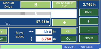
Fig. 23 The current position of the electrode displayed in the area indicated by the red arrows.
6.6.7 Recipes Database
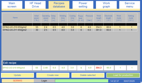 Fig. 24 Recipes Database
All recipes saved in the HMI memory card are listed in the form of a chart. Each row contains one recipe and each column holds one of the recipe’s parameters. The detailed description of the parameters was quoted in the previous chapter. The chart can hold the unlimited number of recipes. Below the chart there is a row titled Edit recipe (on the white background) used for recipes’ edition and creation.
NEW RECIPE
In order to create a new recipe fill in each box in the Edit recipe row and then press Create new key. System should add the newly created recipe to the existing list and display it in the chart’s new row.
 In order to save those changes to a recipe which were made using the Main screen, press the SAVE RECIPE button to copy the parameters from the main screen to the Edit recipe bar in the Recipe database window. The parameters copied may be saved as a new recipe using the Create new button or they can be used to update an existing recipe using the Update button.
RECIPE EDITION
In order to edit a recipe we need to click on the recipe’s name coming from the recipes’ list (selected recipe should be highlighted in yellow and displayed in Edit recipe row). As far as a change of parameter’s value in Edit recipe row is concerned, we need to click on the white box where it should be displayed and enter a new value. Once the edition procedure is completed, the Update key must be pressed and as a result the introduced changes to the indicated recipe will be accepted, saved and stored.
DELETION PROCEDURE
In order to perform the recipe deletion procedure click on the recipe’s name derived from the recipes’ list (selected recipe should be highlighted in yellow and displayed in Edit recipe row) and then press Delete key.
RECIPE SELECTION PROCEDURE
In order to conduct the recipe selection procedure for production purposes choose from the recipes’ list the recipe with values required for duty cycle (selected recipe should be highlighted in yellow and displayed in Edit recipe row) then click on Load for production key as a result the recipe will be uploaded to the system and prepared for use in current production with its parameters displayed in the Main screen window.
SORTING PROCEDURE
The recipes used for production are listed in an alphabetical order. The vertical scrolling bar which allows the operator to view the chart more smoothly will appear on the right side of the chart when a greater number of recipes enters the system. System enables the operator to sort the recipes by name or by each value of a parameter (ascendingly or decreasingly). In order to perform a sorting procedure, find a row of black boxes which should be displayed in the upper part of the chart and click once on a black box located precisely over a column with data that are supposed to be sorted. (Click twice and the direction of sorting will get changed).
6.6.8 Power Setting
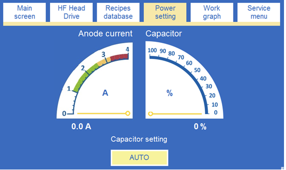
Fig.25 Power Setting
There are two indicators in the window (Fig.25):
Anode current - an indicator of the anode current intensity. It indicates the La anode current intensity which should be equal to the current intensity of the analogue meter which can be found on the control panel.
CAPACITOR – a tool which indicates the position of the output capacitor (within the range from 0 to 100%). With the help of this tool the setting of the appropriate level of power can take place - as a rule the bigger capacity, the higher La anode current is.
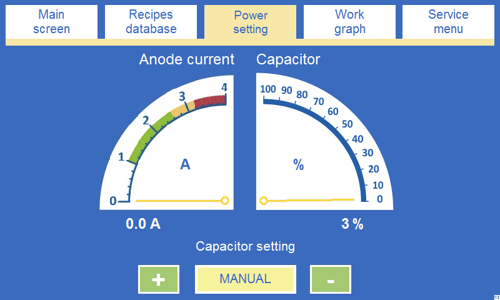
Fig. 26 Power Setting
A group of keys under the indicator (Fig.25 and Fig. 26) is used for the anode capacitor adjustment. The setting can be conducted in two ways:
AUTO – before welding the capacitor is automatically set to the position corresponding to the values entered in the Initial power parameter. When the welding procedure is executed, the capacitor’s position is automatically adjusted so as the level of La anode current intensity could rise to the value inscribed in the Operating power parameter.
 Choose AUTO setting mode during standard duty cycles performed by the machine. MANUAL mode is used for test procedures.
MANUAL – the whole capacitor setting procedure is performed by hand, when the needs arises the operator can change the capacitor’s position with the help of “+” or “-“ keys and at the same time the intensity of anode current is adjusted.
6.6.9 Work Graph
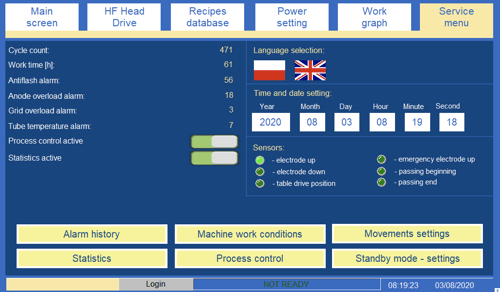
Fig. 28 Service Menu
 Opening the service screen is not possible during the automatic cycle.
In this window (Fig.28) the following pieces of information of statistical origin are displayed:
Cycle count – it is the total number of duty cycles since the machine has been switched on for the first time.
Work time – it is the total time of machine work,
Anti-flash alarm – this value indicates how many times since the day when the machine was manufactured, the protection system against arc-over was switched on.
Anode overload alarm – this value indicates how many times from the day when the machine was manufactured, the maximum level of current intensity in anode circuit was exceeded and as a result how many times the protection mechanism against Anode overload was switched on.
Grid overload alarm – this value indicates how many times from the day when the machine was manufactured, the maximum level of current intensity in grid circuit during weld was exceeded and as a result how many times the protection mechanism against Grid overload was switched on.
Tube temperature alarm – this value indicates how many times since the day when the machine was manufactured, the tube thermal protection system was automatically triggered.
The parameters listed below are available for the Manufacturer’s service technicians and for the supervisor. For this reason, a password is required in order to edit the parameters.
Process control active– this button activates the HF process control algorithm. Each welding cycle is controlled. An alarm will be displayed on the HMI if the welding criteria set has not been reached. The control parameters are in the Process control window.
Statistics active - the active statistics button allows the data, on each partial welding in the cycle, which has been done on the machine, to be collected and saves it in the Statistics window. The status of the welding process, included in the statistics, is described further along in the manual.
Display in inches – the button use to switch between units (centimeters and inches ). The switch is active only for the service.
Additional weld start option – the switch allows to start the welding cycle using two push-buttons (or one of them if a key switch two-hand control is in off position) on the black handles on the operator’s panel (Fig. 5, Fig. 7). The switch is active only for the service.
Control lights showing status of sensors of the machine (Sensors):
electrode up - the control light, switched on, signals that the limit switch showing the upper electrode position is switched on;
electrode down - the control light, switched on, signals that the limit switch showing the lower electrode position is switched on;
table drive position – the activated control signals the drive position of the table and thus prevents the start of welding;
emergency electrode up – the control light, switched off, signals that the electrode encountered resistance while lowered (e.g. it is pressed to the bench) and the limit switch is switched off;
passing beginning – the control light, switched on, signals that the welding head has moved to the beginning of the bench and the limit switch is switched on;
passing end - the control light, switched on, signals that the welding head has moved to the end of the bench and the limit switch is switched on.
The Alarm history button – opens the screen showing the saved history of alarms which have occurred in the machine within the last year. The alarm history is saved in the memory of the HMI panel. The alarm history for each day is saved as a file under the name EL data, e.g. EL_20131122. It is possible to copy the history files from the touch panel’s memory onto a USB device and to view the files in Excel (see section 6.7.6).
 Alarm messages are saved in the language selected in the service menu.
The button marked, Machine work conditions opens a window (Fig. 29), in which the individual parameters of the welding cycle are set, such as:
The set values of all parameters in Machine work conditions are examples.
Pressure max. = Pressure + - this user-defined parameter defines the value of the upper downforce range; upon exceeding the threshold, an alarm will be displayed on the HMI panel. The pressure control starts when the HF process begins.
Pressure min. = Pressure - - this user-defined parameter defines the value of the lower downforce range. An alarm will be displayed once the threshold on the HMI panel has been exceeded; pressure control starts when the HF process begins.
Table delay time [s] – delay time between stopping the welding head and setting the table to the welding position.
Press delay time – this value indicates the amount of time which elapses since the moment the lower limit switch (indicated the lower position of the electrode) is triggered to the moment the electrode is pressed against the material with full strength
Wait time to reach set current (in current weld mode) - the parameter indicating the time the system needs to achieve a given value for the anode current. If the current has not been achieved, within that time, the welding cycle will break and the message, ‘WELDING PARAMETERS NOT REACHED’ will be displayed. This parameter is important only in ‘current’ welding mode.
Power max = Operating power + … – This parameter is only used for controlling the welding process and for determining the upper range of current tolerance. The parameter is adjustable in the range of 0 – 1A.
Power min = Operating power - … – This parameter is only used for controlling the welding process and for determining the upper range of current tolerance. The parameter is adjustable in the range of 0 – 0,5A.
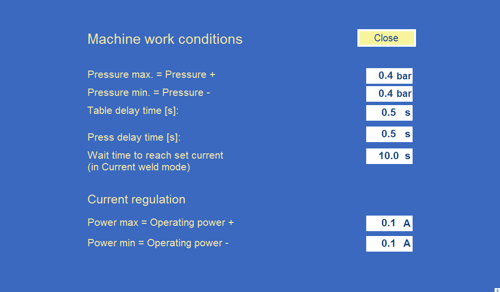
Fig. 29 Machine Work Conditions Window
Movements settings button opens the window (Fig. 30), in which the specific parameters for the driving of the pressure plate, are set, such as:
![]() The set values of all parameters in Movements settings are examples.
The set values of all parameters in Movements settings are examples.
The length of table between stoppers - a parameter to enter the length of the mounted table on which the welding head moves.The entered distance should express the working length of the table (from the left table stopper from the right table stop).
Machine weld head width between limit switches [cm] – a parameter to enter the machine head width between switch limits.
Minimum overlap length [mm] – the minimum overlap length that the user can set in manual and automatic overlap mode.
X - Drive speed AUTO – the parameter determines the speed of passage in X- axis when the machine is working in the automatic cycle (expressed as a percentage of the maximum speed).
X - Drive speed MANUAL – SLOW – the parameter determines the speed of passage in X-axis when the operator moves the machine manually - lightly pressing the joystick (expressed as a percentage of the maximum speed).
X - Drive speed MANUAL – FAST - the parameter determines the speed of passage in X-axis when the operator moves the machine manually - strongly pressing the joystick (expressed as a percentage of the maximum speed).
Y - Drive speed AUTO – the parameter determines the speed of passage in Y- axis when the machine is working in the automatic cycle (expressed as a percentage of the maximum speed).
Y - Drive speed MANUAL – SLOW – the parameter determines the speed of passage in Y-axis when the operator moves the machine manually - lightly pressing the joystick (expressed as a percentage of the maximum speed).
Y - Drive speed MANUAL – FAST - the parameter determines the speed of passage in Y-axis when the operator moves the machine manually - strongly pressing the joystick (expressed as a percentage of the maximum speed).
Set to base axis X - the button starts the process of homing the X axis - determining the zero point for the travel of the head. To start, hold down the button. The homing process is indicated by the button highlight. When the button goes out, the process is finished. During the proces homing, the welding head moves to the left until the limit switch operates and bounces off the limit switch by the length set in the program.
Set to base axis Y - the button starts the process of homing the Y axis - determining the zero point for the travel of the head. To start, hold down the button. The homing process is indicated by the button highlight. When the button goes out, the process is finished. During the proces homing, the welding head moves to the front until the limit switch operates and goes to the base position (about the middle of axis).
![]() During the homing process, the welding head moves within the range of the selected base axis. There must be no obstacle on the machine's travel path.
During the homing process, the welding head moves within the range of the selected base axis. There must be no obstacle on the machine's travel path.
![]() Axis homing should be carried out during:
Axis homing should be carried out during:
- the first after-service startup,
- at the moment of changing the position of limit switch,
- when the place of the element / machine is physically changed (shift of the tensioning chain change).
![]() During the homing process, the welding head moves within the range of the selected base axis.
During the homing process, the welding head moves within the range of the selected base axis.
Inverter regulation gain – a parameter having a direct effect on the speed control of the inverter.
Set position for breaking distance [cm] – The parameter determines the braking distance of the welding head, before it reaches the desired position (expressed in inches or centimeters depending on the position of the unit switch in the service menu).
Axis Y lower limit [mm] – the parameter specifies the minimum distance by which the drive with the head can move backwards, in the direction of the Y- axis (expressed in inches or centimeters depending on the position of the unit switch in the service menu).
Axis Y upper limit [mm] - the parameter specifies the maximum distance by which the drive with the head can move backwards, in the direction of the Y- axis (expressed in inches or centimeters depending on the position of the unit switch in the service menu).
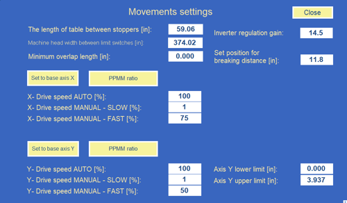
Fig. 30 Movements settings window
Button Process control – this opens the window (Fig. 31) for defining the parameters of the welding process. An alarm will be displayed on the HMI if the welding criteria set has not been reached. The operator can set the individual parameters in the window:
Power max = Operating power + … – This parameter is only used for controlling the welding process and for determining the upper range of current tolerance. The parameter is adjustable in the range of 0 – 1A.
Power min = Operating power - … – This parameter is only used for controlling the welding process and for determining the upper range of current tolerance. The parameter is adjustable in the range of 0 – 0,5A.
Setpoint % for the current which is to be in tolerance – this parameter specifies the percentage value of the time for which the current is required to be within tolerance. When the prescribed percentage threshold has not been reached, an alarm will be displayed on the HMI panel indicating that the welding parameters have not been reached. The parameter is expressed as a percentage, in the range of 0-100%.
Measured total welding time [s]: - this parameter shows the total time taken up by the last weld. The time is counted from the moment the current stored in the recipe has been reached..
Measured welding time when the current was within the tolerance [s]: - This parameter shows the time of the last weld, however, it is only counted for the current within the tolerance range +/- (Power max/min) prescribed in the above parameters.
Calculated value for which the current was within the tolerance [%]: - This parameter shows the percentage of time during which the current was within the tolerance range +/- during the entire cycle.
Pressure max. = Pressure + - this user-defined parameter defines the value of the upper downforce range; upon exceeding the threshold, an alarm will be displayed on the HMI panel. The pressure control starts when the HF process begins.
Pressure min. = Pressure - - this user-defined parameter defines the value of the lower downforce range. An alarm will be displayed once the threshold on the HMI panel has been exceeded; pressure control starts when the HF process begins.
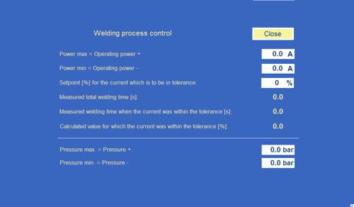
Fig. 31 Welding process control window
Statistics button - opens a window (Fig. 32), in which the statistics of the machine’s operation is collected. Each row in the table relates to one of the partial weld of the machine, while the columns show details of the weld, such as when it was made, what recipe was used, which operator was working on the machine, etc. Detailed information on each weld allows the entire process of a single welding cycle to be traced and learn what values of anode current intensity and pressure were reached. In addition, the table shows previously recorded data. On the right is a drop-down list of dates with each date showing one day of the machine’s operation. To view the data for a given day, the appropriate date should be selected.
Time – time of the recording of the cycle;
Date – date of the registration of the cycle;
1 – Recipe– the name of the recipe used in the registered cycle;2 – Operator – the name of the operator logged-on during execution of the cycle;
3 – Capacitor position [%] – starting position of the capacitor;4 – Delay time [ s ] – set delay time;
5 – Weld time [ s ] set welding time;
6 – Cooling time [ s ] – set cooling time;
7 – Power level [ 1 - 6 ] – set power level;8 – Set anode current [A] – anode current set during the welding process;
9 – Set pressure [ bar ] – set pressure during the welding process;
10 – Work mode [0-1] – the parameter defining the welding work mode. A detailed description of the “Time” and “Current” operating modes is provided on pages 71-72 of the documentation;
11 – Regulation mode 0-1] – the parameter defining the range of automatic adjustment mode of the output capacitor. A detailed description of the 1 (MAX) and 0 (MIN) operating modes is provided on pages 73-74 of the documentation;
12 – Drive mode – welding head drive mode on the worktable. A detailed description of the all drive modes is provided on pages 74,77 of the documentation;
13 – Auto overlap [0-1] – one of two possible options for the calculations of the overlap chosen by means of the Overlap push-buttons. 1 means auto overlap, 0 means manu overlap (see documentation on page 76);
14 – Weld length – the weld length;
15 – Electrode length – the electrode length used in the cycle;
18 – Partial weld number – the number of sectional welds;
19 – Process control active [0-1] – activates or deactivates the HF process control algorithm (see documentation on pages 91-93);
20 – Process status [0-1] – status of the process, where 0 indicates an error - an interrupted processor or welding parameters that have not been reached, 1 indicates success - the welding process ran according to the pre-set parameters;
21 – Current in tolerance [0-1] – parameter defining whether the current value was within or out of tolerance The anode current obtained must be within +/- of the tolerance range of the anode current value for a given percentage of the time for the duration of the welding. 1 means that a tolerance anode current was obtained during welding. 0 means reaching the anode current outside the tolerance range;
22 – Pressure in tolerance [0-1] – parameter defining whether the pressure was within or out of tolerance The pressure obtained must be within +/- of the tolerance range of the pressure value. 1 means that a tolerance pressure was obtained during welding. 0 means reaching the anode current outside the tolerance range;
23 – Average anode current [A] – average anode current during sectional weld;
24 – Average pressure [bar] – average pressure during sectional weld;
25 – Cycle counter - the cycle counter starting from the first machine start up.
![]() The process registration takes place only in the automatic mode.
The process registration takes place only in the automatic mode.
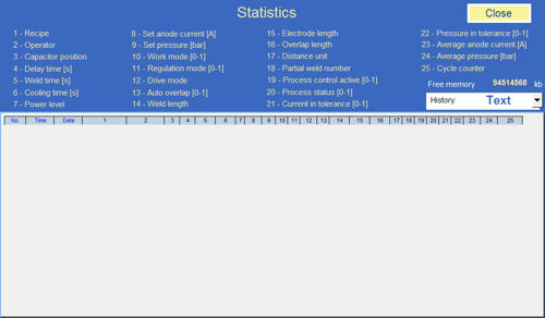
Fig. 32 Statistics window
Button Standby mode – settings - opens a window (Fig. 21) containing tables Electrode heating settings for standby mode. A detailed description of the Standby mode is provided on pages 69-70 of the documentation.
6.7 History and Recipes Files
The following software is required for reading and converting history files and recipes on a computer with Windows operating system:
the free, EasyBuider Pro software, which can be downloaded from the HMI panel from the manufacturer's webpage: http://www.weintek.com/ or representative in Poland http://www.multiprojekt.pl/ftp/weintek_hmi/easy_builder_pro/Microsoft Excel or other spreadsheet programme.
6.7.2 Conversion of history files into xlsx.
To read historical data, it should be downloaded from the memory of the touch panel onto the PC; these should be entered into the appropriate folder; double- click on the file containing the date in question; an xlsx (Excel) file will then be generated. The file presents the historical data of interest in a clear and transparent manner.
6.7.3 Connecting the computer to the machine using WiFi
Each machine is equipped with a WiFi router, which, in turn, is connected to the operator's panel. To connect your computer to this network follow these steps:
On the computer equipped with a wireless network card, select the network with a name corresponding to the factory number of the machine as stored on its nameplate, for example: D650-QE-104.6.7.4 Reading the IP address of the machine to copy recipes and history files
The touch panel is assigned a fixed IP address. To read it, you should:
• Press the icon with an arrow in the lower right corner of the touch panel

• This opens the context menu of the panel

• Press the second icon from the left, a card with the letter 'i'. This will open the 'System Information' window; the IP address needed to create a network connection with the panel will be displayed there.
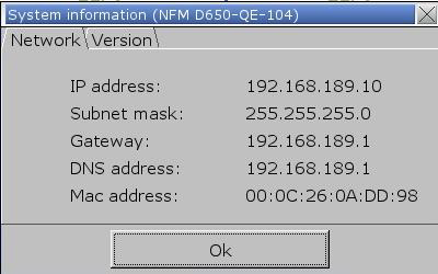
• After saving the IP address, press OK - the window will close.
6.7.5 Copying history files from the HMI panel using the WiFi networkIf your computer is connected to a WiFi network:
• Open Windows Explorer in any folder and enter the following formula in the address bar where the IP address is located, for example: 192.168.189.10; the address read from the touch panel should be entered:ftp://uploadhis:111111@192.168.189.10/

• Then click 'Enter'
• A window containing the touch panel memory will open

• The whole content of each folder can be copied. It is also possible to copy individual files that are stored in the folders.
6.7.6 Data archived in the memory of the HMI touch panelCopying recipes, work history and alarm history onto a USB device:
1. Insert a USB memory device into the port of the HMI touch panel.
2. On the screen of the HMI panel, a window will appear, press Upload.

3. In the next window, select Upload history files, enter the password: 111111 and press OK.
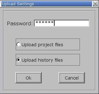
4. Open the folder marked "usbdisk" and select the folder "disk_a_1", then press OK.

In the USB memory, the "history" is saved, containing the folders:
- "datalog"→ "trend" – the folder "trend" contains files with records of the working parameters of the machine. Each day, one file is saved under the corresponding date. To read historical data, insert the USB memory into the computer, then in the "TREND" folder, double click on the required file to generate a file in the xls format (Excel) in order to clearly see the history of the machine’s operation or to generate a graph for a given day. To generate xls files, the free software programme EasyBuider Pro is required; this should be downloaded from the website of the manufacturer of the HMI panel: http://www.weintek.com/.
- "eventlog" – the folder "eventlog" contains files with records of the history of alarms which have occurred during the machine’s operation. The alarm history for each day is saved as a file named EL_data, e.g. EL_20131122. To read historical data, insert the USB memory into the computer, then double click on the required file to generate a file in the xls format (Excel) in order to clearly see the alarm history for a given day. To generate xls files, the free software programme EasyBuider Pro is required; this should be downloaded from the website of the manufacturer of the HMI panel: http://www.weintek.com/.
- "recipe" – the folder "recipe" contains two files with recipes copied from the HMI panel: "recipe.db" and "recipe_a.rcp". The files may be used as backup for the recipes or to save the recipes in another HMI touch panel. It is also possible to edit recipes on the computer.
Editing recipes copied from the HMI panel:
To edit recipes, the free software programme EasyBuider Pro is required; this should be downloaded from the website of the manufacturer of the HMI panel: http://www.weintek.com/.
1. Insert the USB memory- with copied recipes -into the computer and open the Utility Manager application. In the Data Conversion section, choose the application Recipe Database Editor.
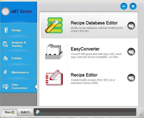
2. In the application Recipe Database Editor click on Import… and select the files with copied recipes "recipe.db".
3. Recipe editing window will open.
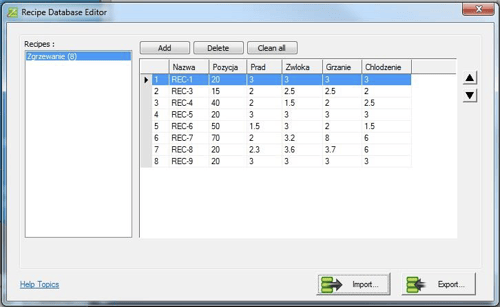
4. When editing is finished, click on Export… and save the file in its previous location.
Copying recipes from USB memory:
- Insert the USB device into the HMI touch panel port.
- On the screen of the HMI panel, a window will appear, click on Download.
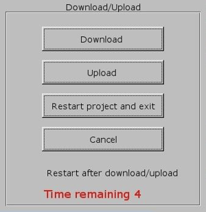
-
In the next window, select Download history files, enter the password: 111111 and click OK.
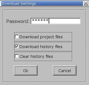
4. Open the folder "usbdisk" and select the folder "disk_a_1", then click OK.

Recipes will be loaded into the memory of the HMI touch panel. Switch the machine off and then on.
The touch panel can also be secured against unauthorized access. It is not possible to work on the machine without the user logging-in to the touch panel.
1. After turning the machine on, click on the "Log-in" button on the touch panel window, on the status bar at the bottom.

2. A contextual window for logging-in will open.

Fig. 33 Login window
3. Select an appropriate user from the drop-down list.4. Enter the appropriate password.
5. Press the Log-in button.
6. The user's name will appear in the field 'Logged-in user'.
7. Press OK and the window will close.
 In the main window, next to the log-in button, the name of the user currently logged-in is displayed.
After the machine is switched off, the user is logged out automatically.
Changing the password assigned to the user.
1. Log in as a user with the authority to change passwords.

2. Press the button 'Change pass'.
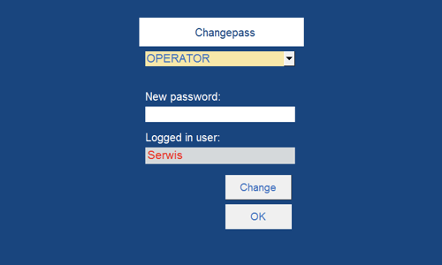
4. Enter the New password.
5. Press 'Change'.
6. Press OK and the window will close.
Factory created users and their assigned password(s)
USER NAME - PASSWORD
SERVICE - INTENDED FOR MANUFACTURER'S SERVICE;
Operator - 100
Supervisor – 111 Permissions:
OPERATOR - can work on the machine, can select recipes, cannot edit recipes and the advanced options machine on the window of the Service Menu.
SUPERVISOR - can work on the machine, select recipes, edit recipes, change parameters, change the passwords of other users.
6.9 Connection to Power Source
 UNDER NO CIRCUMSTANCES should the machine be operated by unqualified personnel. The machine operators must be familiar with the occupational safety and health rules.
Before the machine is connected to a power source the following procedures should be performed:
- Make sure the machine’s working environment (machine’s and its surrounding) is clean and put in order or there are not any obstacles that may adversely influence on the machine’s standard duty cycle; and
- Make sure the adequate amount of raw material (test pieces) is prepared; and
- Make sure the waste bins and containers for welded products are set in the proper place but in close vicinity to the machine due to the Bayer’s requirements applying to the production cycle if any; and
- Make sure all shields are appropriately fixed to the machine and side doors of a switchbox are closed; and
 ATTENTION ! Switchbox doors should be always closed even if the machine is halted.
The machine’s restart procedure is impossible to be performed when the shield is inappropriately attached to the machine or the switchbox doors are open
5. Make sure the EMERGENCY STOP button is unstuck. If the mushroom-headed push button got jammed turn it to the right.
The restart procedure cannot be performer when the EMERGENCY STOP button is jammed (stuck).
7. Make sure the hand-operated compressed air shut-off valve (Fig.9) is turned off, in case the valve should be turned on - turn it to the left - ON position; and
8. Make sure the level of pressure in the pneumatic system is between 0.4 and 0.8 MPa (the rated operating pressure of the machine comes to 0.6 MPa) if the needs arises conduct setting procedure with the help of the compressed air shut-off valve (Fig.9).; and
9. Make sure the MAIN SWITCH is set to 1-ON position and as a result the POWER indicator will start flashing on the control panel; and
 ATTENTION: EMERGENCY STOP button can be pressed at any time of work cycle especially when the emergency shut-down is promptly needed.
10. Make sure the machine is restarted with the help of the blue RESTART key, then wait for 30 seconds within which the machine should become fully activated and get ready for work as the indicator in the light signal column starts flashing green and the progress bar found in the Main Screen of the HMI panel is fully green.
 ATTENTION ! After pressing the RESTART (after turning on the machine) will be basing welding head - the axis motion backward / forward.
 In case the alarm message is displayed even if the machine was restarted see chapter 6.6.2.
11. Make sure the electrode is mounted on the holder.
ATTENTION ! An electrode should be always mounted on the holder when it is going to be closed.
See chapter 6.13. for more information applying to the procedure of Tooling Replacement and Setting.
- Lift the electrode to its upper position.
- Turn the MAIN SWITCH to the position 0-OFF – it means that the machine is switched off.
- Turn off the hand-operated compressed air shut-off valve (in order to implement the procedure - turn the valve to the right - OFF position)
- Put in order the working environment around the machine.
- The electricity power supply plug as well as the compressed air system one should be both unplugged in case long work stoppage (both plugs should be pulled out of the sockets).
6.11 Test and Setting Procedure
ATTENTION ! Test procedure can be performed as long as the machine was appropriately booted - see chapter 6.5.9.The test and setting procedure should be put into practice when:
- the machine has been switched on for the first time,
- the tooling replacement is needed (when the needs arises),
- the maintenance procedure is completed,
- the operators need to be acquainted with the machine’s functionality.
In order to perform the said procedure the operator should:
1. Set the temperature which is to be maintained by the electrode during welding (e.g. 40oC for testing) using ELECTRODE TEMPERATURE thermo-regulator.
2. Go to touch-sensitive panel: HMI → Power setting window → set the capacitor’s setting mode to MANUAL → with the help of “-” and “+” keys make sure the procedure of the capacitor’s position change is performed smoothly at each level of power ranging from 0 to 100%. Once the check-up procedure is completed switch the capacitor’s setting mode to AUTO
3. Set the HF OFF/ON switch to OFF position
4. Upload the appropriate recipe from the memory of touch-sensitive panel: HMI → Recipes database window → highlight the required recipe in the chart → then click on Load for production key or fill in the following boxes of the welding cycle parameters found in the main screen:
- Initial power;
- Operating power;
- Delay time;
- Welding time;
- Cooling time;
- Power level;
6. Press on the HMI panel: HMI → HF Head Drive window → Drive Mode
→ A;
7. Press on the HMI panel: HMI → Main screen → Options → Temp Regulation → on;8. Press on the HMI panel: HMI → Main screen → Work mode → 0 ;
9. Press on the HMI panel: HMI → Main screen → Regulation mode→ 1;
10. Make sure an insulating pad on the work table or on the divider made of aluminum sheet is clean - it cannot be neither dirty nor mechanically damaged in the spot where the electrode is pressed against the welded material;
 ATTENTION ! The insulating pad must be placed directly under the welded material as it is supposed to protect the operator against an electric arc formed between the welding electrode and the work table.
ATTENTION ! If the divider was covered with the insulating pad it should adhere to the table tightly - in such a way that no impurities between the divider and the work table could be found.
12. Carry out homing in the X and Y axe. During the homing, the welding head moves. The homing process is signaled by the backlight of the button.
13. To test the operation of the joystick
 found on the operator pulpit. Move the machine to the right and then to the left. With a light push of the joystick, the machine should move slowly; with a stronger push – it should move more quickly.
14. To test the operation of the joystick
 found on the operator pulpit. Move the head welding to forward and then to background. With a light push of the joystick, the machine should move slowly; with a stronger push – it should move more quickly.
15. Use the button
16. Check in the Service menu window to see if the electrode down indicator is on.
17. If the safety measure, signalled by the message EMERGENCY ELECTRODE UP is activated – the electrode lowered onto the material, will rise spontaneously. In the above case, adjustment of the limit switch indicating the lower electrode position as described in chapter 6.4. should be carried out.
18. Use the button
19. Check in the Service menu window to see if the electrode up indicator is on.
20. Test the raising and lowering of the electrode several times to make sure that it moves smoothly.
21. Lower the welding electrode onto the material and press the START button – the automatic welding cycle should be performed with the high frequency generator switched off.
23. Set the HF OFF/ON switch to ON position,
2. Press on the HMI panel: HMI → Main screen → Regulation mode→ 1 or 0;
 Work mode current / time (1/0) and Regulation Mode min / max (0/1) have been described in detail in chapter 6.6.5.
3. Lower the welding electrode onto the material exactly in the place of the weld.
 ATTENTION: It is possible to stop the welding process repeatedly at any time using the STOP push-button.
4. Press the START button – an automatic welding cycle according to the parameters indicated in the window of the main HMI panel will start. Indications of the ANODE CURRENT gauge should be observed – during welding; the current should increase within the range marked green on the scale of the gauge.
5. When the whole process is completed, the weld quality should be assessed. Practical knowledge is indispensable for correct assessment; hence it is best to seek the advice of the Contractor’s personnel and conduct the first machine start-up with him.
6. If the sealing seam produced is uneven along the whole extension, you will need to read the chapter 6.14.
7. Depending on the effect of the welding (welded, not welded, overheated) welding parameters should be adjusted accordingly:
- Initial power;
- Operating power;
- Delay time;
- Welding time;
- Cooling time;
- Power level;
- Pressure.
8. Make sure the following parameters underwent many hours of testing regarding: work on the same type of material, machine’s work cycle and functionality, machine’s ergonomics standards which are crucial for preventing serious injury during production cycle;
9. Once the weld’s aesthetics and strength parameters are achieved the values should be saved as recipe: HMI → Main screen → click on the SAVE RECIPE button → Recipes database window → enter the recipe’s name in the row titled Edit recipe → press Create new key.
10. Set the HF OFF/ON switch to OFF position,
11. Raise the electrode into its upper position.
12. Press on the HMI panel: HMI → Main screen → Work mode → 0 ;
13. Press on the HMI panel: HMI → HF Head Drive window → Drive Mode → AB;
14. Press on the HMI panel: HMI → HF Head Drive window → Overlap → auto;
15. Spread the material to be welded onto the working bench.
16. Insert weld length onto the touch-panel: HMI → HF Head Drive window → WELD LENGTH (WL).
17. Insert electrode length onto the touch-panel: HMI → HF Head Drive window → ELECTRODE LENGTH (EL).
18. Using the joystick  move it to the position in which the welding should commence and press button
 ![]() to lower the electrode onto the welded material. Making sure that the material is spread correctly;
to lower the electrode onto the welded material. Making sure that the material is spread correctly;
19. Press the START button on the operator’s panel – an automatic welding cycle will commence with the high frequency generator switched off.
20. The machine will weld along the length inserted and will then stop.
21. Press and hold push-button: HMI → HF Head Drive window → Manual Drive → A on the touch-panel – the welding head will move to the position above the first weld.
22. Press and hold push-button: HMI → HF Head Drive window → Manual Drive → B on the touch-panel – the welding head will move to the position above the last weld.
23. Press and hold push-button: HMI → HF Head Drive window→ Manual Drive → GO TO TABLE END on the touch-panel – the welding head will move to the end of the bench.
24. Check whether the passing end control has been switched on in the Service menu window.
25. Press and hold push-button: HMI → HF Head Drive window → Manual Drive → GO TO TABLE BEGINNING on the touch panel – the welding head will move to the beginning of the bench.
26. Check whether the passing beginning control light has been switched on in the Service menu window.
27. Write: HMI → HF Head Drive window → Manual Drive → Move about  , for example 100cm (or 39 inches if the unit switch on the service menu is on inches position) on the touch-panel and then press the Go push-button beside it – the welding head will move 100cm (or 39 inches if the unit switch on the service menu is on inches position) to the right.
 If the entered value is highlighted in red, it means that the welding head cannot be moved by the set value. If the head is not at the edge of the table and it is physically possible to drive, check whether the table length has been correctly entered in the service menu window.
When the Go push-button is pressed, the direction in which the machine moves depends on the entered character, if there is a positive value (without sign) the machine will go to the right, if the entered value is negative, the machine will go to the left.
28. Write: HMI → HF Head Drive window → Manual Drive → Move about  , for example 50mm (or 1,95 inches if the unit switch on the service menu is on inches position) on the touch-panel and then press the Go push-button beside it – the welding head will move 50mm (or 1,95 inches if the unit switch on the service menu is on inches position) to the back.
29. Press and hold push-button: HMI → HF Head Drive window → Manual Drive → A on the touch-panel – the welding head will move to the position above the first weld.
30. Set the HF OFF/ON switch to ON position,
31. Using button to lower the electrode onto the welded material making sure that the material is spread correctly,32. Press the START button on the operator’s panel – an automatic welding cycle with high frequency will commence.
If a special electrode has been installed in the holder that enables welding without the use of a grounding electrode, then after pressing the START button on the operator panel, the grounding electrode will remain in the upper position - it will not lower. After installing this type of electrode, in the main screen will display the message " WELDING WITHOUT GROUNDING FOOT! ".
33. After a complete weld has been made, check whether the partial welds overlap at the place where they do so correctly.34. Having produced the whole sealing seam, one should then check whether the partial seams properly overlap in the overlapping area. If they do not, then one should adjust the electrode’s parallel position as described in the chapter 6.14.
The operator’s first duty cycle is based on the following activities:
1. Boot the machine due to the procedure provided in chapter 6.9.
ATTENTION ! As soon as the booting procedure which was provided in chapter 6.5.9 is conducted successfully the welder will start performing its routine dutiesWelding without insulating pad or when its surface is worn out is not recommended as it may lead to an arc-over causing damage to machine’s tooling.- Initial power;
- Operating power;
- Delay time;
- Welding time;
- Cooling time
- Power Level
- Pressure
- WELD LENGTH (WL) in RF Head Drive window;
- ELECTRODE LENGTH (EL) in RF Head Drive window;
- OVERLAP LENGTH (OL) (optional) in RF Head Drive window. Select the auto overlap (push
 button)
8. Press on the HMI panel: HMI → Main screen → Work mode → 0 or 1;
9. Press on the HMI panel: HMI → Main screen → Regulation mode→ 1 or 0;
10. Then again click on the HMI panel: HMI → Power setting window → set the capacitor’s regulation mode on AUTO position;
11. Prepare material for welding on the work table where the procedure is supposed to be performed;
12. Using the joystick move it into the position where the welding should commence and use button to lower the electrode onto the welded material. Making sure that the material is correctly placed;
13. Push the START button on the control panel – an automatic cycle of welding with high frequency according to the parameters shown in the window of the HMI panel will start. The reading of the ANODE CURRENT gauge should be observed; during welding the current should be increased within the range marked green on the gauge scale.
The welding zone is protected from non-ionizing radiation by the movable grounding electrode which is pressed against the table during the weld procedure and as a result a kind of capacitor which is supposed to limit the non-ionizing radiation is created. The grounding electrode lowers above the welded material when the high frequency is turned on - pressing the START button on the operator panel.
 Particular attention should be paid to the fact that the surface of the material to be welded is evenly distributed on the work table and is not corrugated.
Particular attention should be paid that there are no metal objects near the grounding electrode and under it.
If a special electrode has been installed in the holder that enables welding without the use of a grounding electrode, then after pressing the START button on the operator panel, the grounding electrode will remain in the upper position - it will not lower. After installing this type of electrode, in the main screen will display the message " WELDING WITHOUT GROUNDING FOOT! ".
14. When the work is finished, switch the machine off in accordance with the procedure described in chapter 6.10.
The welding electrode holder is equipped with the automatic quick-fit clamping system controlled from the HMI touch-sensitive panel. It enables the operator to save time and change the electrode without using any instrumentations.
![]() ATTENTION! Mind the weight of the electrode during the electrode’s change procedure. Two people are highly recommended for carrying out the electrode change in case it is big and heavy. Incompetent handling with the electrode may result in the operator’s hands squeeze that may take place when the heavy electrode is taken out from the clamping.
ATTENTION! Mind the weight of the electrode during the electrode’s change procedure. Two people are highly recommended for carrying out the electrode change in case it is big and heavy. Incompetent handling with the electrode may result in the operator’s hands squeeze that may take place when the heavy electrode is taken out from the clamping.
In order to conduct the electrode change procedure implement the following steps:
- Connect the machine to the electric and pneumatic power supplies - machine must be ready for performing the routine duty cycle (meaning that the alarm messages should not be displayed and the electrode should be found in its upper position),
- Set in the panel’s main screen: HMI → Options → electrode → open,
- Move the electrode to the left or to the right (it depends on the machine’s version) - the electrode should slide out of the holders;
- Slide a new electrode over the holders used for clamping, move the electrode to the left or to the right (it depends on the machine’s version)
- Set in the panel’s main screen: HMI → Options → electrode → closed.
6.14 Adjustment of the Sealing Electrode's Parallel Position in Relation to the Table and Sealing Seam Axis
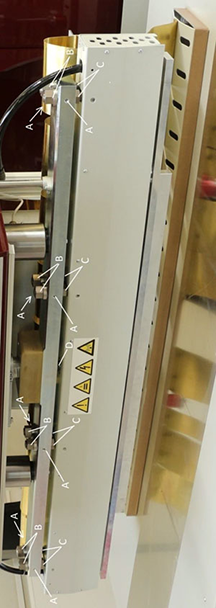
Fig. 34. Electrode grip
Tools required:
Wrench 30
Allen key 4
1. Start the machine, reboot and prepare it for normal operation that is, displaying no alarm messages in the touch-panel and ‘readiness on’. A description for starting the machine is to be found in the chapter: 6.6.2. Check if the sealing surface of the electrode is even and also check whether the electrode:
a. is bent;
b. is twisted;
c. has any indentations;
d. has any protrusions.
Each of the above-mentioned defects will result in an uneven seam, unless they were created explicitly, such as for the tracing of a pattern on the sealing surface of the electrode.
In the event of such a defect, the electrode will need to be repaired.
3. Insert the sealing electrode into the grip and close the grip (see chapter 6.12.4. Prepare the material to be sealed on the working table.
5. Let the electrode down with the use joystick onto the material to be sealed.
6. Check in the Service menu window if the electrode down indicator is on.
7. If it is safe to proceed, as will be signalled by the message EMERGENCY ELECTRODE UP -which will display after letting down the electrode onto the material- it will automatically lift up. One should then adjust the limit switch that points to the lower position of the electrode as described in the chapter 6.4
8. Lift the electrode up and bring it to the upper position.
9. Check in the Service menu if the electrode up indicator is on.
10. Test the electrode several times by letting it down and lifting it up in order to make sure that its movement is smooth.

Fig. 35. Seam with an incorrectly adjusted parallel position of the electrode in relation to the sealing seam axis.
- Lift the electrode up to the upper position.
- Produce a sample seam made from at least two partial seams.
- When the seam is ready, check:
- For evenness along the whole surface – if it is uneven, then one should slightly lower the grip with the electrode, using nuts B and C in those areas where the electrode does not evenly adhere - Fig. 36 (first slightly loosen the relevant nut at B and next, tighten the corresponding nut at C).
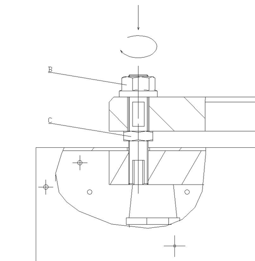
Fig. 36. Regulation of the parallel position of the electrode in relation to the table with the use of nuts B and C (front view of the electrode grip).
- Check whether the beginning of the second seam partly overlaps the end of the first seam - Fig. 35. If they do not overlap, one should adjust the grip with the electrode, parallel to the seam axis, with the use of the screws at A - Fig. 37 (slightly loosen the nuts at B and then slightly loosen the screws at A on the side where the electrode does not overlap with the seam and tighten the relevant screws at A on the other side; also tighten nuts B).
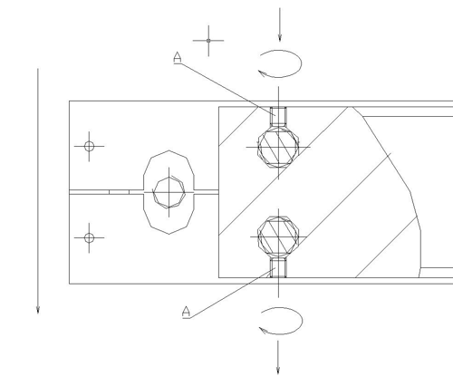
Fig. 37. Adjustment of the parallel position of the electrode in relation to the seam axis with the use of the screws at A (vertical view of a section of the electrode grip).
7.0 Selection Of Weld Parameters
 ATTENTION: The machine should not perform the welding procedure without an insulating pad under the electrode. Due to the appropriately applied insulating pad the number of the over-voltage phenomena forming at the surface of the electrode is decreased.
7.2 Selection of Output Power
In order to achieve the highest level of productivity at the relatively low level of defective welds the machine’s operator should perform the power adjustment procedure for each replaced electrode. The said procedure is performed with the help of the Ua SETTING controls and the Operating power parameter.
Once the power is set and the welding process is initiated the indications of the ANODE CURRENT ammeter are subject to visual inspection. When the measurements are on the increase it means that at this particular moment the welding process begins. The parameter of the weld time should correspond with the value of the parameter due to which the high frequency welding procedure will be stopped as a result of the ammeter's indicating needle stoppage.
When the welding process ends the quality of weld needs to undergo the visual inspection. If the quality of the weld is insufficient the level of power should be increased. In case the above mentioned solution does not bring any fruitful results, then the parameter of time can be increased. However, the value of power should not be too high as it may lead to products, insulating pad and the electrode damage caused by an arc-over.
7.3 Selection of Weld Time Parameters
As a rule, the weld time for materials made of hard PVC should not be longer than 4-5 sec.. Due to the Manufacturer’s experience higher values of the said parameters do not have any influence on the quality of achieved seam but sufficiently deteriorates the process efficiency. If the welding process lasts longer during test procedures it means that the power setting needs to be regulated.
7.4 Electrode Pressure Setting
In order to weld the PVC foil the material should be pressed by the electrode with the pressure strength ranges from 0.5 to 3 kg/cm2. Measuring of pressure strength while selecting the most appropriate value would be too time- consuming and moreover in practice this method would prove useless. Generally, in order to perform the setting procedure successfully, the operator needs to notice some irregularities that come to existence during welding procedure and in seam appearance. When the pressure is too low the following irregularities come to existence:
- susceptibility to spark discharges occurring between two electrodes as the air, which should have been squeezed out, occurs in between two layers of foil and as a result an irregular current intensity is formed;
- occurrence of air bubbles in the seam;
- appearance of seam strength which is small
If the pressure is particularly low, there can occur something usually called “film boiling”. When the film is welded under very low pressure, it can be deformed into a foamy product of very low resistance. Applying excessive pressure is also inappropriate, as it can make the film very thin along the place of welding and thus also result in lower resistance of the welded material. Therefore, it is recommended to follow the principle saying that the thickness of film after welding should be equal to at least half the initial thickness of both layers of film. The appearance and proper shape of characteristic leakage that is usually formed along both edges of the welded place has also significant influence on the resistance properties of the welded material. If such a leakage does not appear, it usually indicates insufficient resistance of the welded place, which can be very easily tested. The lack of the leakage after the welding process can be caused by applying too low output power or insufficient pressure. If you use electrodes with cutting edges, it is very important to position the cutting edge correctly. It is usually assumed that the cutting edge of the electrode should protrude from the welding plane by about half the thickness of welded film. In order to check the operation of the cutting edge, it is necessary to make several test welding cycles and remove the film scraps. The result of tests can be considered satisfactory when removing the film scraps along the line of welding takes no more than one cut with scissors.
8.0 Maintenance
Owing to the applied construction solutions and uncomplicated structure of the machine, both preventive and emergency maintenance and control activities are relatively simple and do not require long breaks in the operation of the machine.
The welding machine requires small amount of work connected with machine
operation and maintenance, provided that appropriate conditions of use are maintained. It is necessary to regularly check the technical condition of the machine connection to the mains, particularly the condition of electrical shock protection system.
All components of the high-frequency generator, particularly all insulating elements, must be kept clean. You should thoroughly clean the interior of the output system of the generator at least once every three months. Upon such cleaning, the condition of generator components and units that directly cooperate with the generator should be checked and all the connections should be tightened.
Due to specific properties of the machine, it is recommended that some of the aforementioned tasks are performed by authorized and properly qualified technical service personnel of the Manufacturer (it applies particularly to emergency situations). The aforementioned tasks require particular care and attention.
ATTENTION: During the operation of the generator, its components, as well as the components of the output circuit, have the voltage up to 8 kV DC and the high-frequency voltage up to 480 V (27.12 MHz ).
ATTENTION: The capacitors of the anode generator can hold electric charge of the voltage up to 8000 VDC even after the welding machine is disconnected from the power supply. Before touching the components of the high-frequency generator, these capacitors must always be discharged.
Grounding of the machine structure must be performed with particular care. Remember that the generator must never operate when the protection screens are removed, also during technical service and maintenance activities, when the safety level of the machine may be lower due to the repair being performed.
Any and all maintenance tasks and repairs require a permit of the authorized persons.
You should keep a MACHINE RECORD, including the dates and types of performed preventive activities or repairs.
During the maintenance tasks or any other required manual operations, never enter or put any body parts to the area exposed to potential and predictable hazards, in order to eliminate the risk of potential and predictable hazardous situations.
ATTENTION: Any work in within the zone of active pressing unit of the machine, ie. device replacement can be executed with special precaution measurements only by trained service team.Always wear protective clothes and anti-slip footwear, reducing the risk of falling. Always ensure that your sleeves are well tightened around your wrists or properly rolled up.
Always use working gloves when working with components with sharp edges.
The entire personnel responsible for operation and maintenance of the machine should be properly trained and instructed.
Each and every maintenance or repair operation can be performed exclusively by authorized and qualified personnel, capable of correct interpretation of defects and failures, reading installation diagrams and technical drawings, in order to ensure that all disassembly and assembly operations connected with standard maintenance procedures are performed in a professional and – most importantly - safe way.
All tasks performed in the area of operation of the pressing unit, i.e. assembly and disassembly of the electrode, performed when the power supply of the machine is on, can be carried out exclusively by the personnel properly trained in Occupational Health & Safety, including particularly the risk involved in the operation of the pressing unit.
You should also predict the potential non-standard behavior of the machine, when the pneumatic system of the welding machine or the compressed air supply ducts are unsealed. It will result in slow automatic lowering of the pressing unit of the welding machine.
The personnel should be informed about such a risk during the training in Occupational Health & Safety.
ATTENTION: During each and every of the aforementioned operations the machine operation must be stopped.
8.2 Preventive Program - Periodic Checks
ON THE BEGINNING OF EVERY SHIFT
- Check whether the operating area of the machine is clean and tidy;
- Visually check whether or protection screens are locked;
- Check lighting of the operating area;
- Check whether the EMERGENCY STOP button work properly;
- Check the main protection in electrical installation;
- Check the condition of copper and brass conductive elements in the area of the electrode holder and grounding elements of side protection screens.
EVERY 100 HOURS OF MACHINE OPERATION (AT LEAST ONCE A WEEK):
- Check whether the load-bearing screws (including particularly the screws fastening the tools) are properly fastened and tightened;
- Check the condensation water level in the compressed air filter container; if there is water, empty the container; if there are large amounts of solid contaminants, disassemble and wash the container;
EVERY 500 HOURS OF MACHINE OPERATION (BUT AT LEAST EVERY TWO WEEKS)
- Check whether the anode lamp radiator is clean;
- Check the amount of solid contaminants and dust in the generator chamber; if it is necessary, clean the chamber using a vacuum cleaner or a compressed air gun;
- Check whether moving elements (including particularly the tools and guides) are clean;
- Grease moving elements – particularly the guides; if it is necessary, use solid lithium-based grease and a greaser;
- Check and test the alarm unit.
EVERY 1000 HOURS OF MACHINE OPERATION (BUT AT LEAST EVERY SIX MONTHS)
- Visually check the condition of mechanical elements;
- Tighten all screws;
- Check whether the electric shock protection measures works properly;
- Check the effectiveness of greasing of guides;
- Check the condition of the main contact elements – main contacts or other contact elements of the system, such as contacts or relays of excessively worn surfaces must be replaced.
EVERY 5000 HOURS OF MACHINE OPERATION (BUT AT LEAST EVERY SIX MONTHS)
- replace oil heating electrode – oil type L-LH-46.
ATTENTION: Prior to each maintenance turn off the machine using MAIN SWICH and disconnect main power.
 IT IS FORBIDDEN to lubricate the machine during operation.
9.0 Occupational Health & Safety
9.1 Basic Requirements
- The machine may be used exclusively in a way appropriate for its purpose explicitly described in Item 1.
- The applied construction solutions related to safety reduce to the minimum both the non-standard behavior of the machine and the hazards to the operators and other persons having contact with the machine, provided that the principles of safe work are observed. The machine is equipped with key switches on protection screens, whose disassembly requires specific tools, including the switch on the door of the welding chamber, EMERGENCY STOP button and moving protection screens enclosing the welding area for the time of the welding process.
- The issues connected with Occupational Health & Safety and the assessment of risk during the contact of a person with the machine have been described in detail in the previous chapters of this manual.
- As this issue is extremely important, some instructions are repeated in this section.
- Every new employee that has contact with the welding machine should be trained in the field of basic principles of occupational health & safety and familiarized with the types of hazards involved in the operation of the welding machine, unless the operator follows the obligatory regulations and principles.
- The personnel responsible for operation of the welding machine must have thorough knowledge of first aid in cases of electric shocks and burns. In the case of persons working with devices using electromagnetic waves of the frequency in the range of 0,1 - 300 MHz, periodic medical examinations are required.
- After the installation of the welding machine, it is necessary to measure the electromagnetic field emission and set the borders of the hazardous area.
- On the basis of the measurement results, the level of hazard and the time for which operators can remain in the hazardous area are determined in accordance with applicable standards.
- Only the operators who have appropriate approvals for working in the area exposed to electromagnetic field based on specialized medical examinations and have been properly trained in the safe operation of the devices emitting electromagnetic field can enter the hazardous zone.
- The aforementioned measurements should be performed by an authorized institution. Detailed instructions concerning such measurements are specified by the applicable regulations in the country where the machine is used.
- Machine operators should always wear standard work clothes, gloves, headgears and anti-slip footwear.
- The working environment of the machine, the floor and the manual holders and grips must be always clean and free of any contamination, grease or mud, in order to reduce the risk of slipping or falling to the minimum possible level.
- Never use the machine in the automatic mode of operation without the fixed or mobile protection elements. Check regularly whether all emergency switches and all other protection elements are properly mounted and function properly.
- Every operator of the machine must be instructed on the functions of the protection elements of the machine and their proper use.
- In the area surrounding the machine (about 1.5 m around the machine), there can be no items that might interfere with the operation of the machine. This area must be kept clean and have proper lighting.
- Never use the machine’s manipulators or flexible pipes as holders. Please remember that any accidental moving of the machine’s manipulator can accidentally start the machine’s operation.
- Always inform the supervisor and / or traffic personnel about any and all cases of incorrect operation of the machine.
- Any and all maintenance tasks and repairs require a permit of the authorized persons.
- You should keep a Machine Record, including the dates and types of performed preventive activities or repairs.
- During the maintenance tasks or any other required manual operations, never enter or put any body parts to the area exposed to potential and predictable hazards, in order to eliminate the risk of potential and predictable hazardous situations.
NEVER USE THE WELDING MACHINE WHEN THE PROTECTION SCREENS ARE REMOVED OR WHEN THE KEY SWITCHES ARE BLOCKED. IT PARTICULARLY APPLIES TO THE PROTECTION SCREENS OF THE GENERATOR.
Those protection screens reduce the electromagnetic field emission and prevent accidental touching of the elements of the electrical circuit having power supply voltage or high voltage up to 8000 V.
- Always wear protective clothes and anti-slip footwear, reducing the risk of falling. Always ensure that your sleeves are well tightened around your wrists or properly rolled up.
- Always use working gloves when working with hot components or components with sharp edges.
- One should also remember that on those components that have not been covered behind any shield for ergonomic reasons, i.e. the electrode and the conductive components of the electrode holder, there is high-frequency voltage. NEVER TOUCH THOSE COMPONENTS DURING THE WELDING PROCESS.
- Touching those components during the welding process results in burning of the skin with high-frequency voltage. It is not, however, dangerous to life or health.
- The adopted method of power supply of the welding machine poses a potential risk of pressing or crushing limbs in the space between the pressing of the electrodes. Any and all works in the area of operation of the pressing unit, i.e. assembly and disassembly of electrodes or spreading and removing the material and scrap, which are performed when the welding machine is connected to power supply can be done exclusively by employees trained in the field of occupational health & safety, including the information on risk posed by the pressing unit.
- During operation of the machine the operator should be in area shows below
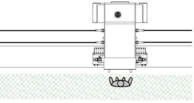
Fig. 38. ZDWA-15-C-3 - safety working area (green color)
9.3 Conditions Of Occupational Safety Of Personnel Responsible For Maintenance And Repairs Of The Welding Machine- These works require particular care. One must always remember that capacitors of the anode generator can hold electric charge of the voltage of 8000 V even after the welding machine is disconnected from the power supply network. Before touching the components of the high-frequency generator, these capacitors must always be discharged.
- During the operation of the generator, its components, as well as the components of the output circuit, have the high-frequency voltage. Grounding of the machine structure must be performed with particular care. One must also remember that the time of the generator’s operation with the protection shields removed must be reduced to the minimum.
- All repairs must be performed in accordance with the prevailing principles of repair and operation of devices by a person having an appropriate certificate issued by the appropriate Electricians’ Association (in Poland: SEP).
- The entire personnel responsible for operation and maintenance of the machine should be properly trained and instructed.
- Each and every maintenance or repair operation can be performed exclusively by authorized and qualified personnel, capable of correct interpretation of defects and failures and reading installation diagrams, in order to ensure that all disassembly and assembly operations connected with standard maintenance procedures are performed in a professional and – most importantly - safe way.
- During each and every of the aforementioned operations the machine operation must be stopped.
TAKE ALL THE NECESSARY STEPS TO PREVENT:
- Using of the machine in any other way than as described in this Operation & Maintenance Manual,
- Incorrect installation, not performed in accordance with the procedures described in this manual,
- Inappropriate operation of the machine or its operation by personnel without appropriate training,
- Machine supply of inappropriate parameters,
- Insufficient maintenance of the machine,
- Unauthorized alterations or interference by persons without the required licenses, permits or training,
- Using spare parts other than original ones,
- Any actions by any persons that are not in accordance with the principles specified in this Operation & Maintenance Manual and any warning information.
10.0 Electrical Documentation
10.1 Power Supply Parameters - Technical Data
|
Power supply |
3 x 220 VAC; 50/60 Hz |
|
Installed capacity |
22 kVA |
|
HF power output |
15 kW |
|
Operating voltage |
24 VDC |
|
Operating frequency |
27.12 MHz |
|
Main overcurrent protection |
63A |
|
Frequency stability |
+/- 0.6 % |
|
Generator lamp (metal-ceramic triode) |
ITL 12-1 |
|
PLC control system |
DELTA |
|
Anti-discharge circuit system |
complete ANTIFLASH with HF Filter |
10.2 Electrical Installation Concept Design Drawings
See Appendices
11.0 Pneumatic Documentation
11.1 Technical Data
|
Operating pressure |
0.4 – 0.8 MPa |
|
Compressed air consumption |
Max. 70 nl (standard) per cycle |
|
Air purity |
according to ISO8573-1:4-4-4 |
|
Filtering performance |
20 um (ISO8573-1 4-4-4) |
11.2 Operating Principle
- drive of the pneumatic holders of the electrode;
- drive of the grounded electrode;
- press unit;
- holders for electrode.
Furthermore, the pneumatic system consists of an air preparation system: pressure filter and reducer, soft start, connection elements, discharge valve and throttle-check valves. The air is supplied through the discharge valve to the VFRL unit; it is pre-filtered and reduced to the required volume. Next, it is supplied through electrically- or electro pneumatically-controlled distribution valves to appropriate pneumatic actuators initiating their movement. The dynamics of the movement of actuators can be adjusted using throttle-check valves mounted on the actuators. The sequence of the movement of actuators is controlled by the controller of the welding machine.
11.3 Operation ManualIMPORTANT: The presence of the air treatment system installed in the machine does not free the Client from obligation to ensure the air purity conforming to Class 4-4-4 in accordance with ISO8573-1.SEE APPENDICES
12.0 Disposal
12.1 General Instructions
The applied construction solutions and the high-quality components enable proper operation of the machine for the period of about 30 years. However, there might occur some changes in the needs of the Client or changes in the principles or standards that cannot be predicted today, which might require a disposal of the machine before the end of the aforementioned period. It also applies to replaced or repaired parts or components of the welding machine.
The Client is obliged to ensure that the disposal of the machine or its components is performed in accordance with applicable legal requirements prevailing at a given moment and in a given place.
All components of the machine are recyclable.
Disposal of hazardous wastes must always be performed by specialized companies.
Types of wastes produced during the device’s life cycle are described below in Item 12.2.
12.2 Wastes
- Pieces of cloth or paper saturated with substances used for cleaning of the machine components;
- Used spare parts of the generator, depending on the material they are made of;
- Liquid or solid grease wastes;
- Grease remaining after greasing or maintenance of the machine;
- Generator lamp.
ATTENTION: the lamp contains rare-earth metals and rare-earth metal oxides that are highly toxic. In the event of breaking, the lamp must be disposed with utmost care and with the help of specialized services.
All wastes produced in the course of replacement or technical service activities, which are contaminated with grease, cannot be disposed of together with industrial wastes.
IT IS PROHIBITED to put wastes in garbage bins, directly dispose of them in any other way or dispose of them by standard garbage collection services. 12.3 Procedure Of Disassembling The Machine Before Disposal
- Position the machine so that it stands motionlessly.
- Disconnect power supply of the machine.
- Disconnect compressed air supply of the machine.
- Remove flexible plastic or rubber ducts and ensure its disposal by a specialized company.
- Disconnect and remove wires and electrical devices and ensure its disposal by a specialized company.
- Segregate steel components and components made of non-ferrous metals and ensure their disposal by a specialized company.
13.0 Appendices
13.1 Model And Serial Number Tag
Each Miller Weldmaster machine has this sticker located on the rear of the machine. It identifies the model and serial number of each welder.
It will also state the voltage and hertz required for operation.