Version 2.0
Updated: 2/10/2025
This instruction manual is intended to be a guide when operating the T300 Seam welder. To ensure optimal performance from your welder, please follow the recommendations and specifications precisely.
Table of Contents
- Chapter 1: Intended Use
- Chapter 2: Explanation of Warnings
- Chapter 3: Electrical and Air Requirements
- Chapter 4: Principles of Heat Sealing
- Chapter 5: Definition of Controls
- Chapter 6: Recommended Replacement Parts
- Chapter 7: Machine Specifications
- Chapter 8: Maintenance
- Chapter 9: Transportation Specs and Storage
- Chapter 10: Technical Requirements
- Chapter 11: Additional Machine Documents
For more technical information regarding this machine call our Resolution Center at 1-855-888-WELD or email service@weldmaster.com.
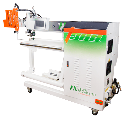
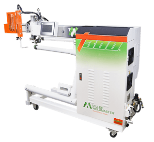
T-300 hot air and hot wedge fabric welding machine.
1.0 Intended Use
The T300 is a rotary hot wedge welding machine intended to heat-seal weldable thermal plastics such as:
- Vinyl (PVC) laminated and coated fabrics
- Vinyl (PVC) and Polyurethane (PU) films
- Polyurethane (PU) and Polypropylene (PP) coated fabric
- Polyethylene (PE)
- Thermoplastic rubber (TPR) film and fabrics
- Non-woven Polyester and Polypropylene
- Various Fusing Tapes
- Weldable Webbing
- Rigid Extruded Products
The manufacturer does not approve of:
- Any other uses for these machines.
- The removal of any safety guards while in operation.
- Unauthorized modification of the machines.
- Using replacement parts that are not manufacturer-approved.
 Only a properly-trained technician may operate and/or perform any routine maintenance or repairs to the machines.
NOTE: The manufacturer will not be held liable for any damage or injuries occurring from any inappropriate use of this machine.
2.0 Explanation of Warnings
There are several different warning symbols placed on the Miller Weldmaster T300. The symbols are to alert the operator of potentially hazardous areas on the machine. Familiarize yourself with their placement and meaning.

Caution: Hot
The “Caution: Hot” symbol is placed on a guard near hot surfaces.

Danger: Weld Roller Pressure Point
The “Wel Roller Pressure Point” symbol is placed near any potential pinch points. Do not place any body parts near these sections of the machine while the machine is running.
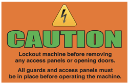
Caution: Unplug Machine
The “Caution: Unplug Machine” sticker is placed near the opening of the cabinet and all access panels. To prevent electrocution, the machine should always have the power disconnected before the cabinet door is open.

Warning: Keep Hands Clear
The“Warning: Keep Hands Clear” sticker is placed on the Heater Assembly. To prevent any pinching or burns, be aware of the location of your hands at all times.
3.0 Electrical and Air Requirements
Warning! Only a qualified electrician may connect the electrical power.
Preparation - World Power
-
Make sure the Power Supply is at 230v, 25amp, 50/60hz or 400v, 16amp, 50/60hz and the Pressure Supply comes up to 120 psi (8.3 bar) when the machine is working.
-
Make sure the voltage and current is dedicated to the machine and to the above specification.
-
An appropriate ground connection must be made to the ground terminal provided on the machine.
-
Before operation of the machine be sure the surrounding area of the machine is free of flammable debris. Only authorized persons should be in the area of the machine while in use.
-
In the event of an emergency, press the Emergency Stop Button.
Electrical Supply
Due to the number of different style outlets available, the cord will not include a plug. It is recommended that your electrician install a plug that is comparable to your style power outlet. You may choose to have your power cord hard-wired into your Power Supply. It is recommended that your electrician use a Junction Box with an ON/OFF switch. The Miller Weldmaster T300 requires one of the following electrical requirements:
- 25 Amp - Single phase - 230 Volts
- 16 Amp - Single phase - 400 Volts
Shop Air Supply
The Miller Weldmaster T300 includes an In-Shop Air Supply Valve that allows quick connects and disconnects to your shop air supply. Due to the number of different style airline connectors, a male quick-connect is not included. You will want to select a male quick-connect with a ¼ inch NPT (National Pipe Thread) to match your female quick-connect. The Miller Weldmaster T300 requires the following shop air requirements:
- Minimum of 5 cfm at 120 psi
- Not to exceed 140 liters/min at 8.3 Bar
- An in-line water and dirt separator
4.0 Principals of Heat Sealing
Heat
Hot Air Heating System
The Heat required for the welding operation is created electrically by one heating element located inside the Heat Element Housing. The Internal Air Compressor pumps air over the heat element and carries the heat through the Hot Air Nozzle, applying the heat to the material to be welded. The hot air temperature ranges from 25 to 730 Degrees Celsius (100 to 1350 Degrees Fahrenheit).
Hot Wedge Heating System
The Hot Wedge heat system uses four cartridge heat elements to electrically heat the Wedge. The Hot Wedge temperature ranges from 25 to 450 Degrees Celsius (100 to 842 Degrees Fahrenheit).
Speed
The Speed of the Weld Rollers determines the amount of time the heat is applied to the material being welded. The slower the speed setting, the more the material will be heated. The faster the speed setting, the less the material will be heated. To achieve the best weld, a minimal amount of heat should be applied to the material while still achieving a full weld. Too much heat will cause distortion of the material; while not enough heat will prevent the material from welding.
Pressure
The pressure of the weld roller is the final step when creating a weld. The pressure of the weld roller compresses the heated material together completing the welding process.
Precision
The welding head has precise positioning thanks to a motor that positions the welding head exactly where it is needed. Using the controls on the HMI; you are able to adjust and place the head with the push of a button.
Summary
When heat sealing, the correct combination of heat, speed, pressure, and precision will allow you to achieve a properly welded seam.
5.0 Definition of Controls
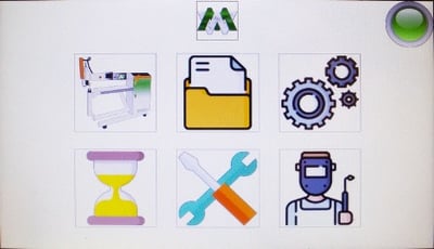
Main Screen - HMI Operation

Machine Operator Screen:
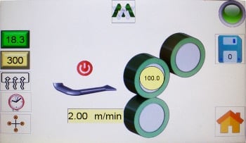
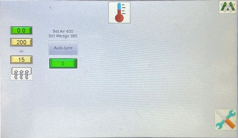
 Actual Temperature: This is how hot the machine is currently. The temp can be adjusted by pressing the number on the screen and inputting the speed you want.
**This is an example of where the actual temperature is located. The true temperature you need will vary depending on the product and material.
 Temperature Set Point: This is how hot you want the machine to be for the purpose of welding your thermal plastics. The temp can be adjusted by pressing the number on the screen and inputting the speed you want.
**This is an example of where the Temp. Set Point temperature is located. The true temperature you need will vary depending on the product and material.
 Heat Switch: This is for turning the Temperature Controller ON/OFF.
 Drive Delay: Once the foot pedal is pressed, the drive start delay time will delay the weld roller from turning until the set point is reached.
![]() Heat Swing On or Off: Turns Swing On and Off.
Heat Swing On or Off: Turns Swing On and Off.
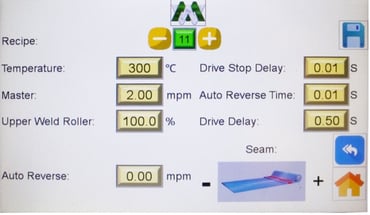
 Master Speed: This is the speed of the weld rollers. The speed can be adjusted by pressing the number on the screen and inputting the speed you want.
**This is an example of where the Master Speed is located. The true speed you need will vary depending on the product and material.
 Upper Weld Roller Speed: This increases the speed of the top roller compared to the lower master roller. 100% is 1 to 10
The T300 has an Upper Weld Roller Speed adjustment that allows you to vary the synchronization of the upper weld roller to the lower weld roller. There will be situations that occur where the upper roller will need to rotate at a faster rate than the lower roller. Some examples would be; welding a hem, welding a pole pocket, and welding a straight piece to a radius piece. To increase the speed of the upper roller, follow these steps:
-
-
- Press the menu button in the Main
- Press the welding functions button in the Menu
-
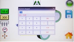
To adjust the Upper Weld Roller Speed percentage, you can push the up or down arrows to increase or decrease the speed, or press the box with the percentage and a numeric keypad will appear. Select the numeric value desired.
Puller on: This activates the outboard puller
Puller Speed: This is similar to the upper weld roller speed. You typically want this running the same slightly faster than the master rollers to stretch material fast
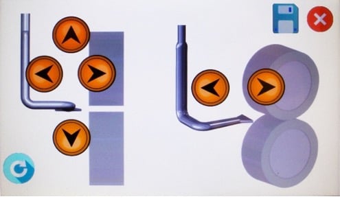
Heat Swing Adjustment: This allows you to adjust the position of the head mechanically by using the arrows
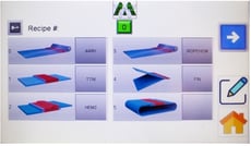
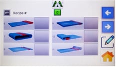
![]() Recipe: This is a particular combination of the parameters of heat and speed used to weld different types of fabric. This shows which recipe you’re currently using on the machine. 0 - 24 Available recipe settings. In order to change recipes, the heat on/off switch must be in the off position.
Recipe: This is a particular combination of the parameters of heat and speed used to weld different types of fabric. This shows which recipe you’re currently using on the machine. 0 - 24 Available recipe settings. In order to change recipes, the heat on/off switch must be in the off position.
 Settings:
 Engages the table and puller with the 2 front rollers. Best for long, straight seams
 Engages the puller. Swing arm down. Best for inflatables or curved products
 Single Roller Beam. Takes the table off and going to swing this underneath by dropping the lower weld roller and changing the setup
 Auto-Reverse: This adjusts the reverse speed of the rollers when the machine stops welding. This function is to minimize missed welding and make a perfect product. The UP and DOWN arrows increase and decrease the reverse speed.
 ON/OFF Switches: The Drive FWD/REV, Drive System ON/OFF, and Foot Pedal Override ON/OFF switches are used to turn the functions ON/OFF.
 Foot pedal Control: You can hold the foot pedal to control the rollers and when you release the head swings out of position. Or you can press and it runs and press again to release
 Hours Meter: The hour meter manages how long the machine has been running. Broken our between the machine, maintenance, hot air, and hot wedge
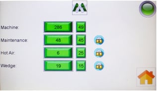
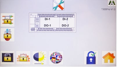
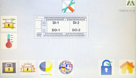
 Advanced Settings: The tools button leads into the depth menus - some things are locked off for parameters
- Functions: screen brighten the screen
- how you change your swinging motion.
- combination of different speeds of how you're going in when it's going left to right.
- up down left right functions in out speed.
- Different combinations can make your watch swing straight, or swing in from the sidewall depending on what you're going for.
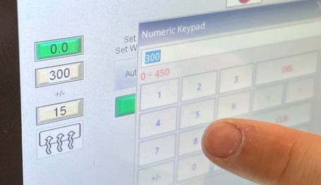
Note: Anytime you switch between heat systems, you must go to this menu, and you want to auto-tune it. We have a note up here that says when you're doing the hot air, you need to set it to 300 then click the auto-tune. Hot wedges will be 200.
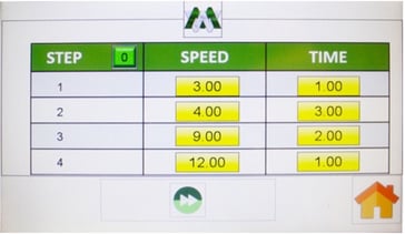
 Weld Test: time of the duration for each one. The wedge is going to be in position, and you can test the material at different speeds to see where your best weld is It’s the best way to test to see if you're getting to weld well.
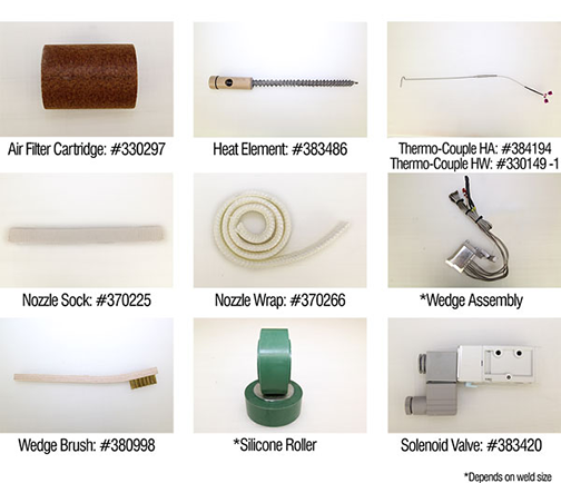
6.0 Recommended Replacement Parts
Miller Weldmaster recommends keeping the following spare parts in stock:
NOTE: There are two different PID parameters saved in the machine according to heating system used, hot air or hot wedge. Press the Default for 1 second, and the PID will go back to the factory settings.
Parts Order? Call 855-888-9353 or email service@weldmaster.com
The T300 is a heat sealing machine which welds thermal plastic fabrics or films by Hot Air or Hot Wedge, through applying pressure, consistent speed, and accurate temperature for perfectly sealing thermal plastic materials.
Features
- Suitable for multiple-sized tents, inflatable boats, banners, tarps, awnings, and etc.
- User Friendly HMI allows the operators to easily adjust the machine for a wide variety of products.
- Auto-Control Temperature controller allows the system to accurately provide heat to the products being produced.
- Dual Pedal Control allows for easy operation for extended periods of time with high efficiency.
- An automatic Auto Reverse function allows the machine to start and stop with a void free seam.
Technical Specifications
- Amp Rating - 25amp at 230volt / 16amp at 400 volt
- Rated Power - 4000 W
- Rated Voltage - 230v AC, 50/60hz or 400v AC, 50/60hz
- Maximum Temperature - 1350°F (730°C)
- General Air Pressure - 120psi (8.3 bar)
- Machine Speed - 3 ft/min to 80 ft/min (1 m/min to 25 m/min)
- Overall Dimensions - 69in x 26in x 58in (1750mm x 650mm x 1450mm)
- Seal Width - 5mm to 50 mm
- Maximum Noise - 70 dbA
- Net Weight - 730lbs (330kg)
- Electrical Document Number - The documentation number is the serial number of the machine. This number is located on the serial tag on the machine.
Mechanical Section
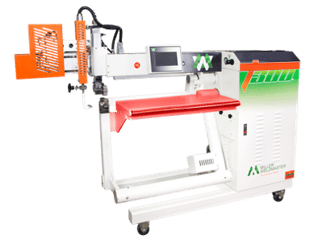
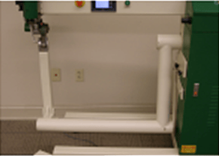
- Removable Roller Table Top: The roller table top assembly is used for paneling applications, edging, edge finishing, and general seaming applications.
-
Installing/Removing/Adjusting Table Assembly
- Begin by loosening the two black knobs to the right of the operator (removal of these knobs is not necessary).
- Next go around to the puller side of the machine. Just beneath the material puller there will be two black knobs similar to the fasteners previously loosened. Remove these knobs while supporting the weight of the table assembly.
- Lastly, lift up and pull the table assembly out of the throat of the machine through the backside (puller side).
-
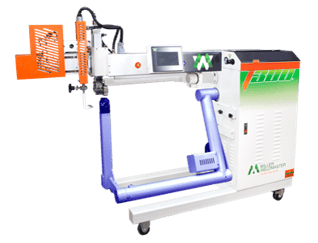
- Swing Arm: The swing arm is used when products include shapes, curves, and tubes of the seaming area. Can be positioned up or down.
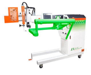
- Single Roller Beam: The single roller beam is best for products that have tight curves. Easy to move the material through the machine.
Heat Source
- Hot Air: heat element housing contains the heating element and thermal-couple.
- Hot Wedge: hot wedge tip contains the heating elements and thermal-couple.
- Upper Unit: Upper Weld Roller up and down motion.
- Heat System Adjustment Assembly: Allows for accurate positioning of the Hot Air Nozzle or wedge tip.
- Outboard Fabric Puller Assembly: Assists operator with material handling while producing flatter seams.
.png?width=475&name=Untitled%20design%20(7).png)
Operator Controls Section
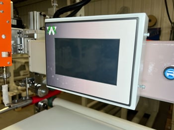
- Control Panel: The HMI (Human Machine Interface) Digital Touch Screen allows you to set system controls.
- Power On/Off Button: Power button turns the machine on and off.
- Emergency Stop: The emergency stop button, when depressed, will stop the seaming operation in the event of an emergency.
Pneumatic System
- Pressure Adjustment Regulator: Filters out water and dirt in the air. The Pressure Adjusting regulator, regulates the pressure to the machine. Increase the pressure by rotating clock-wise, and decrease the value by rotating counter-clockwise.
- Solenoid Valve: Controls the actions of the Air Cylinders.
- Pressure Gauge: Used for displaying the pressure setting. The Upper Weld Roller gauge is used for displaying the pressure setting of the Upper Weld Roller.
- Air Cylinder: The upper unit/puller Air Cylinders are used for opening and closing the weld roller and puller roller. The heat system cylinder controls swing-in and swing-out of the heat system.
- Puller Pressure Limit Control: Reference page 21 for adjustment procedure.
Other
- Power Supply Circuit Breaker: Used for the protective control of the General Power Supply of the complete machine.
- Right Pedal Switch: It controls the lifting of the weld roller, and the opening and closing of the weld rollers and puller (if the puller switch is on).
- Left Pedal Switch: Controls the starting and stopping of the seaming operation.
8.0 Maintenance
Daily: Oil Rail


- Operator should oil the rail located on the welding head daily. This will help to keep the heat system running smoothly
- Oils, greases, or low-viscosity greases can be used as lubricants
- Lubricants containing MoS2 or graphite cannot be used
Warning! The operator must disconnect the power from the machine before proceeding.
Electrical Element
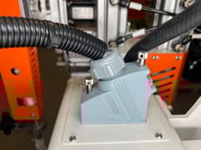
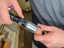
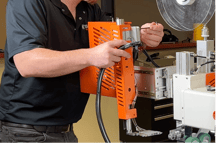
1. Turn the power off on the machine and remove the grey phoenix plug located beside the black air hose on top of the machine (shown in picture).
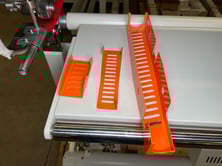
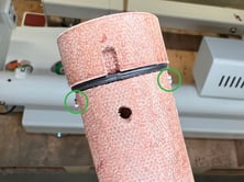
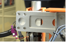
2. Remove the 11 screws that hold the orange heat guard in place. Once removed it should be in 3 pieces as shown in the picture.
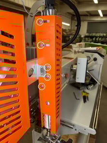
3. Loosen the plastic hex nuts to expose the 2 lead wires going into the heating element.
4. Unscrew the green and yellow ground wire.
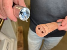
5. Pull the silver cap off of the top corked portion of the heating element.
6. Loosen the two set screws shown in the picture to remove both lead wires
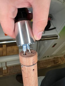 .
. 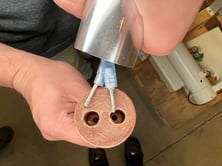
7. Slide the old heat element out of the housing and put the new element in its place.
Electrical Circuits
- When replacing parts and components, you must use the part or components of the same type as the original or equivalent to the original type. Original equipment replacement parts should be purchased through Miller Weldmaster and or a Miller Weldmaster authorized distributor.
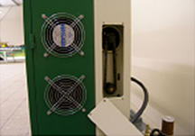
- The electrical cabinet must be cleaned every six months. To properly clean the electrical cabinet: disconnect the power supply, using compressed air and a blow gun, gently blow air across the electrical component and control cabinet cleaning dust and debris from the area.
- To avoid damaging the PLC, Display and Operating Panel, never plug or unplug the cables connecting the PLC, Display and Operating Panel while the power is on.
- If there is any fault that cannot be removed, please immediately contact the service department at Miller Weldmaster.
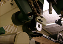
Drive System
- Check if the Driving Sprockets are dislocated or loosened.
- Check if the chains are too loose. Tighten as needed.
- Check if the nozzle is parallel with and at the center of the Weld Roller. If not, it shall be adjusted as per Hot Air Heat System Adjustment.
- Check if the up and down movement of the Upper Unit is smooth.
NOTICE: The glass tube is easily broken and can already be broken, be very careful.
Cleaning/Replacing Air Filter (For Hot Air Machines Only)
The Miller Weldmaster T300 has an external air compressor that supplies airflow to the heat element. Periodic cleaning and changing of the Air Filter Cartridge is necessary to maintain sufficient airflow. Insufficient airflow or any impurities in the airflow will shorten the life of the heat element.
Clean Air Filter Cartridge Every Week
If the surrounding conditions in your production area are not clean, it is recommended that you clean the Air Filter Cartridge twice a week.
- Loosen and remove the Air Filter Cartridge End Cap.
- Remove the Air Filter Cartridge.
- Using brake cleaner or a product containing high amounts of Ether, spray the Air Filter Cartridge from the inside out.
- Dry the Air Filter Cartridge by blowing the Air Filter Cartridge from the inside out with shop air.
- Reinstall the Air Filter Cartridge and Air Filter Cartridge End Cap onto the internal air compressor and tighten.
Replace Air Filter Cartridge Every 3 - 6 Months
If the surrounding conditions in your production area are not clean, it is recommended that you change the Air Filter Cartridge every month.
- Remove the Air Filter Cartridge End Cap.
- Remove the Air Filter Cartridge.
- Replace with a new Air Filter Cartridge, part number 330297.
- Reinstall the Air Filter Cartridge and Air Filter Cartridge End Cap onto the internal air compressor.
Tightening/Oiling Chains
The Miller Weldmaster T300 has several chains that are used to drive weld rollers and puller rollers. Although not a high maintenance item, chains should be inspected once a year to ensure there is not excessive corrosion, rust, or dirt. Also inspect for any looseness or slack. If needed, lubricate chains once a year with 80w – 90w gear oil.
1. Turn the circuit breaker to the off position.
2. Disconnect the power cord from the power supply. If the power cord is hard wired, shut the power supply off at the junction box.
3. Remove the cover on the end cabinet and inspect the chains. Perform any maintenance to the chains as needed.
4. Remove the end caps on the lower beam and inspect the chains. Perform any maintenance to the chains as needed.
5. Remove the out puller cover and weld roller upper unit covers. Perform any maintenance to the chains as needed.
Replacing Wedge Tip
1. Remove power to the machine by switching the main circuit breaker to the off position.
2. Ensure the wedge has cooled down to a temperature that can be handled.
3. Loosen and remove the housing cover.
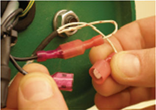
4. Disconnect the male from the female leads on the thermocouple and wedge wires.
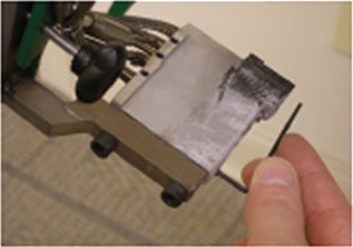
5. Loosen the two set screws located on the side of the wedge.
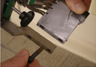
6. Remove both bolts from the rear mounting bracket and remove the wedge assembly.
7. Install the new wedge assembly reversing the above instructions. When tightening the bolts to the rear of the wedge, loosen by a 1/8 of a turn so the wedge has some “float” to it.
Hot Air Heat System Adjustments
Begin by turning your hot air on and setting to the desired temperature. Set weld rollers to the closed position by engaging the Weld Roller Pedal.
- Left to right nozzle position, check this by engaging the Drive Foot Pedal and watch the tip of the nozzle. It should be centered left to right on the weld rollers, if so, move on to next alignment step. If not, locate the left to right Lockdown Knob and loosen by two turns. This will allow adjustment of the left to right Micrometer. Now locate the left to right Micrometer which is located about eye level with the operator. Rotating the left to right Micrometer Knob so the numeric value is increasing will move the nozzle tip to the left. Rotating the left to right Micrometer Knob so the numeric value is decreasing will move the nozzle tip to the right. After the nozzle is centered on the weld rollers, tighten down the left to right Lockdown Knob.
- Up and down nozzle position, check this by engaging the Drive Foot Pedal and watch the tip of nozzle. It should be pointing at the pinch point of the two weld rollers, if so move on to next alignment step. If not locate the Height Lockdown Knob and loosen by two turns. This will allow us to adjust the Height Micrometer Knob. The Height Micrometer Knob is located at the bottom of the heat system pointing downward. Rotating the Height Micrometer Knob so the numeric value is increasing will raise the nozzle tip. Rotating the Height Micrometer Knob so the numeric value is decreasing will lower the nozzle tip. After the nozzle is aligned, tighten down the Height Lockdown Knob.
Note: Nozzle tip will move up or down when heat is changed. After a heat change of more than 100 degrees, be sure to check height of nozzle tip. - Depth of your nozzle should be at approximately ¼ - ½ of an inch from the pinch point of your weld rollers. Check this by engaging the Drive Foot Pedal and watch the tip of nozzle. If the nozzle is aligned, perform a test weld. If not locate the Depth Lockdown Knob and loosen by two turns. This will allow us to adjust the Depth Micrometer Knob. The Depth Micrometer Knob is located on the back of the heat system facing the direction of fabric flow. Rotating the Depth Micrometer Knob so the numeric value is increasing will move the nozzle tip closer to the weld rollers. Rotating the Depth Micrometer Knob so the numeric value is decreasing will move the nozzle tip away from the weld rollers. After nozzle is aligned, tighten down the Depth Micrometer Knob. When the nozzle is aligned, perform a test weld.
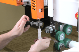
Puller Adjustments
- With the table assembly in place, adjust the height of the material puller by using the steel collar and lock nut to achieve the desired height of the material puller.
- For most applications the material puller wheel should first be adjusted until it is slightly touching the stainless steel roller.
- Next adjust the puller wheel slightly lower by turning the adjusting collar one half turn counterclockwise. This will ensure full contact of the mating surfaces.

Hot Wedge Heat System Adjustments
A note before beginning; the wedge should be a bit loose (3/16 inch of play). Begin by setting the Master Speed to zero and closing the weld rollers.
First Alignment Step
When the wedge arm swings in and drives forward, it is imperative that the point of the Alignment Pin fits into the Recess of the wedge arm. Check this by engaging the Drive Foot Pedal. If this is OK, move on to the second alignment step. If not, locate the Centric Adjustment Knob on top of the wedge arm. By loosening the Centric Adjustment Knob, you will be able to rotate the Knurled Shaft by ¼ turns until the Alignment Pin fits into the Recess. Tighten the Centric Adjustment Knob when proper alignment is achieved.
Second Alignment Step
The tip of the wedge must be the same height as the pinch point of the weld rollers. Check this by engaging the Drive Foot Pedal and watching the tip of the wedge. It should drive straight to the pinch point of the weld rollers without touching the top or bottom weld roller first. At the same time, the tilt of the wedge needs checked. Ensure that the left tip is not placed higher or lower than the right tip. You must inspect this by getting eye level with the weld rollers. If these are OK, move on to the third alignment step. If not, locate the Height Lockdown knob and loosen by two turns. This will allow adjustment of the Height Micrometer Knob. Rotating the Height Micrometer Knob so the numeric value is increasing, will raise the wedge. Rotating the Height Micrometer Knob so the numeric value is decreasing will lower the wedge. Adjusting the tilt requires a combination of loosening and tightening the Left Tilt Knob and the Right Tilt Knob. After the wedge tip height and tilt is aligned, tighten down the Height Lockdown Knob.
Third Alignment Step
The tip of the wedge must be aligned left to right, and centered on the rollers. Check this by engaging the Drive Foot Pedal and watching to see if the tip is centered on the rollers after it drives forward. If this is alright, move on to the Fourth Alignment Step. If not, locate the Left/Right Lockdown Knob and loosen by two turns. This will allow the adjustment of the Left/Right Micrometer Knob. Rotate to decrease the numeric value on the Left/Right Micrometer Knob will move the wedge to the right. Rotate to increase the numeric value on the Left/Right Micrometer Knob will move the wedge to the left. After the wedge tip is aligned left to right with the weld rollers, tighten down the Left/Right Lockdown Knob.
Fourth Alignment Step
The tip of the wedge must be squared to the weld rollers. Check this by engaging Drive Foot Pedal and looking over the top face of the wedge. See that the wedge squares evenly with the weld rollers. If this is aligned properly, move on to the Fifth Alignment Step. If not, slightly loosen the Wedge Mounting Bolts, very slightly rotate the entire heat system in the desired direction and retighten the Wedge Mounting Bolts. Check the wedge squareness again. Keep repeating until the Wedge is mounted square.
Fifth Alignment Step
The last step involves the wedge depth. Check this adjustment by engaging the Drive Foot Pedal to check the contact between the wedge and the weld rollers. Not enough contact, and the wedge will barley touch the rollers. This will cause there to be a lack of heat transfer through to the material. Too much contact, the wedge will come into contact with the rollers and the upper swing unit of the wedge will deflect. This will cause the wedge to be sucked in by the weld rollers during seaming. If aligned properly, turn the heat switch on and set up for a test weld. If not, locate the Depth Lockdown Knob and loosen by two turns. This will allow for the adjustment of the Depth Micrometer Knob. Rotating the Depth Micrometer Knob to increase the numeric value will move the wedge back away from the weld rollers. Rotating the Depth Micrometer Knob to decrease the numeric value will move the wedge towards the weld rollers. When aligned properly, tighten down the Depth Lockdown Knob. Turn the Heat Switch on and set up for a test weld.
Changing the Heat System between Hot Air and Hot Wedge:
First thing you’ll want to do is to unplug our phoenix plug.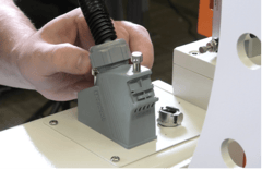
Unscrew the four bolts that’s behind the Hot Wedge Heat System.
Take it out and replace it with the Hot Air Heat System by screwing in the four bolts, plugging in the phoenix plug along with plugging in the air hose.
Now that the Hot Air is set up, we’ll need to install the nozzle into the heat system.
Swing the Heat System into position
insert the nozzle in, clamp it tight and square it up to the weld roller.
Once that’s set up, you’ll want to go to your HMI screen to adjust the alignment of the nozzle.
Start by moving it to the left, adjust it down and bring it into the weld rollers.
Unlike the Wedge, you will have a gap behind it so you won’t be able to touch the wheels.
Click your save button, and return to the home page.
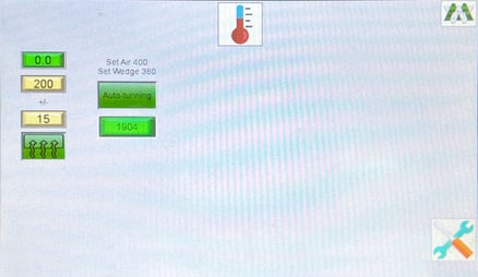
***IMPORTANT NOTE: When changing the heat system from hot air to hot wedge or vice versa, you are required to autotune your machine:
- Turn or Keep Heat turned off
- Set temp to 200 Degrees
- Press Auto Turn Function
- This will turn the heat on by itself
- This will turn the heat on by itself
- During auto-tuning - do not touch the machine or try to operate it.
- Allow the machine to run the cycle
- Allow the machine to run the cycle
- Heat will remain on once auto-tune has completed its cycle
- Temperature should remain stable with a +/- 5 Degrees
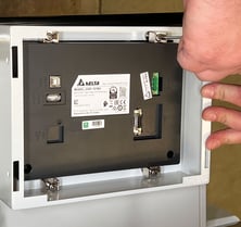
Replace HMI Battery
**To replace HMI Battery - Always leave power on when replacing to ensure all factory settings are saved. If not left on while replacing the battery, you risk the loss of memory and programs.
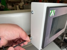
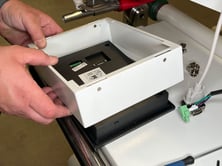
1. Remove the side cover Allen bolts on both sides of the HMI Screen
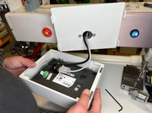
2. You then will be able to remove the HMI screen from the back plate
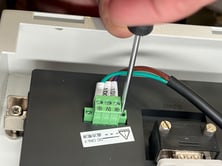
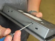
3. Take a small flat heat screw driver to loosen the green power plug screws located on each side (do not remove any of the screws securing the 3 wires in place)
4. Once the screws are removed you will be able to unplug or pull out the green power plug
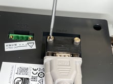
5. Loosen the knurled set screws to the HMI cable (VGA Cable)
6. Now that your HMI has been unplugged you can unscrew the 4 corner screws to the back cover plate of the HMI and this will remove the frame from the screen
7. You can now take a flat head screwdriver and press in the 3 tabs and remove the 1 screw holding the back plate
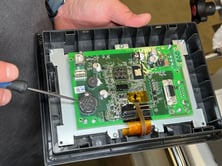
8. You will now have access to the circuit board which holds the battery
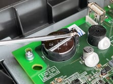
9. The battery can now be removed by taking a small flat head screwdriver to release the battery
Replace Battery
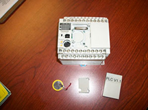
When replacing the PLC battery it is important to have the machine POWER ON during the entire procedure to ensure there is no memory loss.
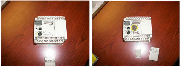
1. Remove access cover from PLC.
2. Remove battery cover
3. Remove battery.
4. Install new battery and put on the access cover. The machine should be good to proceed with normal operation.
9.0 Transportation Specs and Storage
Warning! It is recommended to use a forklift when moving or removing a crated machine from a pallet.
Transporting Within a Production Facility
Due to the weight of the Miller Weldmaster machine, the manufacturer requires a forklift or tow motor to be used. The forks are to be inserted below the bottom frame along the center of gravity. Lift slowly to ensure proper placement of forks.
Transporting Outside Production Facility
The manufacturer requires the Miller Weldmaster machine to be placed on a pallet and loaded into a truck using a forklift or tow motor. The forks are to be inserted below the bottom frame along the center of gravity. Secure the machine to the pallet and protect the various controls and features by crating the machine.
Storage
The manufacturer recommends that any time the machine is not in use, it must be protected from excess dust and moisture. The operator should familiarize themselves with the warning symbols on the machine to be alert to the potentially hazardous areas on the machine.
NOTE: The manufacturer will not be held liable for any damage or injuries occurring from any inappropriate use of this machine.
10.0 Technical Requirements
Technical Requirements
- Total air pressure should be 120 psi (8.3 bar).
- The pressure of the Upper Unit Weld Wheel should be between 5 psi and 60 psi (.3 bar and 4.1 bar).
- The lifting of the Upper Weld Roller must be smooth and free, without obvious vibration.
- When the Upper/Lower Weld Rollers are aligned properly, the edges of the two rollers should be parallel and aligned.
- Heat System Swing: The swing in/out of the heat system should be smooth and natural at moderate speed.
- Air lines and air fittings should be free of leaks.
NOTE: Changes in factors such as thickness of materials, qualifications of the operators and different environment and weather may directly affect the product. The operator should be able to understand the following adjustable factors particularly:
- Heating Temperature
- Air Pressure
- The pressure of the Upper Weld Roller
- Air volume
- Placement of heating system
11.0 Additional Machine Documents