This instruction manual is intended to be a guide when operating the T3 Extreme Seam welder. To ensure opti- mal performance from your welder, please follow the recommendations and specifications precisely.
Table of Contents
- Chapter 2: Explanation of Warnings
- Chapter 3: Electrical and Air Requirements
- Chapter 4: Principles of Heat Sealing
- Chapter 5: Definition of Controls
- Chapter 6: Operation
- Chapter 7: Adjustment
- Chapter 8: Welding Tips
- Chapter 9: Accessories
- Chapter 10: Maintenance
- Chapter 11: Recommended Replacement Parts
- Chapter 12: Transportation and Storage
- Chapter 13: Additional Machine Documents
For more technical information regarding this machine call our Resolution Center at 1-855-888-WELD or email service@weldmaster.com.
1.0 Intended Use
The T3 is a rotary hot wedge welding machine intended to heat-seal weldable thermal plastics such as:
- Vinyl (PVC) laminated and coated fabrics
- Vinyl (PVC) and Polyurethane (PU) films
- Polyurethane (PU) and Polypropylene (PP) coated fabric
- Polyethylene (PE)
- Thermoplastic rubber (TPR) film and fabrics
- Non-woven Polyester and Polypropylene
- Various Fusing Tapes
- Weldable Webbing
- Rigid Extruded Products
The manufacturer does not approve of:
- Any other uses for these machines.
- The removal of any safety guards while in operation.
- Unauthorized modification of the machines.
- Using replacement parts that are not manufacturer-approved.
![]() Only a properly-trained technician may operate and/or perform any routine maintenance orrepairs to the machines.
Only a properly-trained technician may operate and/or perform any routine maintenance orrepairs to the machines.
NOTE: The manufacturer will not be held liable for any damage or injuries occurring from any inappropriate use of this machine.
2.0 Explanation of Warnings
There are several different warning symbols placed on the Miller Weldmaster T3. The symbols are to alert the operator of potentially hazardous areas on the machine. Familiarize yourself with their placement and meaning.
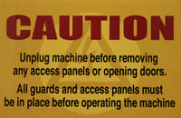
Caution: Unplug Machine
The “Caution: Unplug Machine” sticker is placed near the opening of the cabinet and all access panels. To prevent electrocution, the machine should always have the power disconnected before the cabinet door is open.

Caution: Electricity
The “Caution: Electricity” sticker is placed near areas that contain electrical.

Caution: Read Document
Read accompanying documentation before use.
3.0 Electrical and Air Requirements
Warning! Only a qualified electrician may connect the electrical power.
Electrical Supply
Due to the number of different style outlets available, the cord will not include a plug. It is recommended that your electrician install a plug that is compatible to your style power outlet. You may choose to have your power cord hard-wired into your power supply. It
is recommended that your electrician use a junction box with an ON/OFF switch with short circuit protection as required by local electrical code to be suitable for the primary disconnect. The Miller Weldmaster T-3 requires the following power supply.
•16 Amperes - Single phase - 230 Volts
Shop Air Supply
The Miller Weldmaster T-3 includes an in-shop air supply valve that allows quick
connects and disconnects to your shop air supply. Due to the number of different style airline connectors, a male quick-connect is not included. You will want to select a male quick-connect with a 1⁄4 inch NPT (National Pipe Thread) to match your female quick-connect. The Miller Weldmaster T-3 requires the following shop air requirements:
•Minimum of 3 cfm at 120 psi (standard) or 85 liters/min at 8.3 Bar (metric)
4.0 Principals of Heat Sealing
Heat
Hot Air Heating System
The Heat required for the welding operation is created electrically by one heating element located inside the Heat Element Housing. The Internal Air Compressor pumps air over the heat element and carries the heat through the Hot Air Nozzle, applying the heat to the material to be welded. The hot air temperature ranges from 25 to 730 Degrees Celsius (100 to 1350 Degrees Fahrenheit).
Hot Wedge Heating System
The Hot Wedge heat system uses four cartridge heat elements to electrically heat the Wedge. The Hot Wedge temperature ranges from 25 to 490 Degrees Celsius (100 to 915 Degrees Fahr- enheit).
Speed
The Speed of the Weld Rollers determines the amount of time the heat is applied to the material being welded. The slower the speed setting, the more the material will be heated. The faster the speed setting, the less the material will be heated. To achieve the best weld, a minimal amount of heat should be applied to the material while still achieving a full weld. Too much heat will cause distortion of the material; while not enough heat will prevent the material from welding.
Pressure
The pressure of the weld roller is the final step when creating a weld. The pressure of the weld roller compresses the heated material together completing the welding process.
Summary
When heat sealing, the correct combination of heat, speed, and pressure will allow you to achieve a properly welded seam.
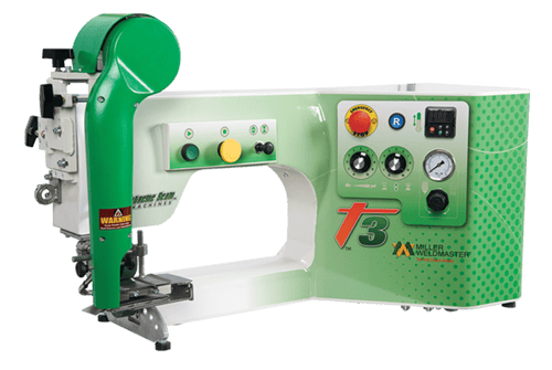
5.0 Definition of Controls
The manufacturer suggests that all operators are familiar with all the controls of their machine. It is in the operator's best interest to know the purpose of all these controls and their functions.

Start Button: The start button initiates the wedge swing and motor controls. By depressing the start button the welding process will begin.

Stop Button: The stop button will pause the welding operation. By depressing the stop button the welding operation will stop.
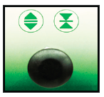
Weld Roller Open/Close: The push/pull knob will open or close the weld rollers. By pushing the knob the weld rollers will close. By pulling the knob the weld rollers will open.

Emergency Stop Button: The emergency stop button will stop the system operations in the event of an emergency. Depress the emergency stop button in the event of an emergency. Twist to release the emergency stop button.
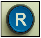
Reset Button: The reset button turns power ON to the control system of the machine. The reset button must be pushed after the power disconnect has been turned ON and after the emergency stop button has been turned and released.
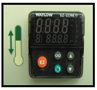
Temperature Controller: The temperature controller is used to set the desired temperature of the wedge. The temperature range is 0OC to 430OC. The UP arrow increases the set temperature, the DOWN arrow decreases the set temperature. The EZ, scroll, and double circle buttons are used for programming functions. The top display is of the actual temperature and the bottom display is of the set temperature. If the display is not showing the set and actual temperatures, turn the power disconnect to the OFF position for 30 seconds then back on again.
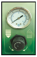
Pressure Gauge and Regulator: The pressure gauge and regulator displays and controls the weld roller pressure. To increase or decrease the weld roller pressure, pull the regulator knob out then rotate. Rotate clockwise to increase the pressure and counter clockwise to decrease the pressure. Push the regulator in to lock the knob in place.
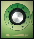
Speed Control: The speed control adjusts the speed of the weld rollers. 0 is the lowest speed and 10 is the fastest speed. Turn the knob to the desired speed setting.
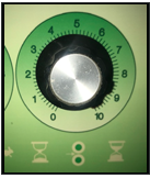
Drive Delay Control: The drive delay control delays the weld rollers from starting until the start button or foot pedal has been depressed. The drive delay control should be set to allow the wedge to be in proper position before the weld rollers begin to turn. Adjustment will be needed for individual products being welded.
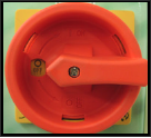
Power Disconnect: The power disconnect turns power ON/ OFF to the machine. For power to be turned ON rotate the handle to the ON position and to turn OFF turn to the OFF position. The power disconnect should always be turned OFF when the machine is not in use or being serviced.
Foot Pedal Plug: The foot pedal plug connects the foot pedal to the control system of the machine. Insert the male end of the plug into the female end of the plug, then tighten the threaded nut finger tight. The foot pedal should be connected only when the machine is used in a stationary mode.
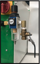
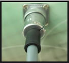
Air Supply: The air supply should be connected to the supply side of the ball valve, 1/4" NPT. The ball valve should be turned to the horizontal position whenever the machine is not in use and locked in the OFF position when the machine is being serviced.
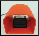
Foot Pedal: The foot pedal initiates the wedge swing and motor controls. By depressing the foot pedal the welding operation will begin.
6.0 Operation
NOTE: Before starting up the machine, please check it carefully and guarantee that there are no foreign objects under the welding area. Be sure the surrounding area of the machine is free of flammable debris. Only authorized persons are permitted to use machine.
Start Up
1. Connect the power cord to the appropriate power supply.
2. Connect air to the appropriate air supply and turn the air supply ball valve to the OPEN position.
3. Turn the power disconnect to the ON position. This will power up the machine and the heat system.
4. Make sure the emergency stop button is released.
5. Depress the reset button. Depressing the reset button turns ON the control system of the machine.
6. Assuming the machine adjustments and control settings are to the desired point, the machine is ready for use.
Shut Down:
1. Turn the power disconnect to the OFF position. This will power down the machine and the heat system.
2. Turn the air supply ball valve to the OFF position.
Wedge Adjustment
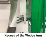
Wedge placement is the most important component with wedge welding. When the wedge arm swings in and drives forward, it is imperative that the point of the alignment pin fits into the recess of the wedge arm. Before adjusting the wedge system be sure the weld roller pressure is set to the desired pressure setting. For most application the weld roller pressure should be set to 40-50 psi. Check this by engaging the drive foot pedal. Having correct placement will ensure a proper weld.
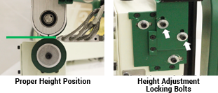
Wedge Height Adjustment
Before checking the wedge alignment, set the speed control to its lowest setting, the drive delay to its highest setting, and close the weld rollers.
1. Swing the wedge into place by depressing the drive foot pedal or the start button. Once the wedge swing has reached the weld position, view the placement of the wedge with respect to the weld rollers then release the drive foot pedal or depress the stop button.
2. The height of the wedge must be level with the pinch point of the weld rollers.
3. If the height of the wedge is high or low of the pinch point an adjustment will be required.
4. To adjust the wedge height alignment the wedge must first be in the home position.
5. Locate and loosen the height adjustment locking bolts and adjust the wedge system up or down depending on required level position of the wedge to the pinch point.
6. After adjustments have been made, re-check the position of the wedge with respect to the weld roller pinch point. See step one.
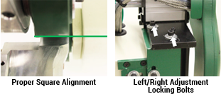
Wedge Squareness Alignment
Before checking the wedge alignment, set the speed control to its lowest setting, the drive delay to its highest setting, and close the weld rollers.
1. Swing the wedge into place by depressing the drive foot pedal or the start button. Once the wedge swing has reached the weld position, view the placement of the wedge with respect to the weld rollers then release the drive foot pedal or depress the stop button.
2. The squareness alignment of the wedge must be on center line with the weld rollers.
3. If the squareness of the wedge is rotated off the center line of the weld rollers an adjustment will be required.
4. To adjust the wedge squareness, the wedge must first be in the home position.
5. Locate and loosen the left/right adjustment locking bolts and adjust the wedge system rotation depending on required position of the wedge to the weld rollers.
6. After adjustments have been made, re-check the position of the wedge with respect to the weld rollers. See step one.
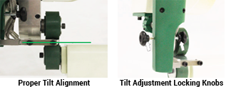
Wedge Tilt Alignment
Before checking the wedge alignment, set the speed control to its lowest setting, the drive delay to its highest setting, and close the weld rollers.
1. Swing the wedge into place by depressing the drive foot pedal or the start button. Once the wedge swing has reached the weld position, view the placement of the wedge with respect to the weld rollers then release the drive foot pedal or depress the stop button.
2. The tilt of the wedge is best viewed from the operators perspective, eye level with the wedge and weld roller pinch point when the wedge has swung into place.
3. If the tilt alignment of the wedge is not horizontal with the pinch point of the weld rollers an adjustment will be required.
4. To adjust the wedge tilt alignment the wedge must first be in the home position.
5. Locate and loosen/tighten the tilt adjustment locking knobs
and adjust the wedge system left or right depending on required position of the wedge to the weld rollers. For example, if the wedge tilt requires movement to the left then first loosen the tilt knob on the left one or two turns, then tighten the tilt knob on the right. This will adjust the wedge tilt to the left.
6. After adjustments have been made, re-check the position of the wedge with respect to the weld rollers. See step one.
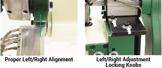
Wedge Left/Right Alignment
Before checking the wedge alignment, set the speed control to its lowest setting, the drive delay to its highest setting, and close the weld rollers.
1. Swing the wedge into place by depressing the drive foot pedal or the start button. Once the wedge swing has reached the weld position, view the placement of the wedge with respect to the weld rollers then release the drive foot pedal or depress the stop button.
2. The squareness alignment of the wedge must be on center line with the weld rollers.
3. If the squareness of the wedge is rotated off the center line of the weld rollers an adjustment will be required.
4. To adjust the wedge squareness, the wedge must first be in the home position.
5. Locate and loosen the left/right adjustment locking bolts and adjust the wedge system rotation depending on required position of the wedge to the weld rollers.
6. After adjustments have been made, re-check the position of the wedge with respect to the weld rollers. See step one.
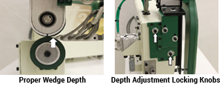
Wedge Depth Alignment
Before checking the wedge alignment, set the speed control to its lowest setting, the drive delay to its highest setting, and close the weld rollers.
1. Swing the wedge into place by depressing the drive foot pedal or the start button. Once the wedge swing has reached the weld position, view the placement of the weld with respect to the weld rollers then release the drive foot pedal or depress the stop button.
2. The depth alignment of the wedge must be in contact with the weld rollers to allow contact and heat transfer to the fabric.
3. If the depth alignment of the wedge is back too far or too far into of the pinch point of the weld rollers an adjustment will be required.
4. To adjust the wedge depth alignment the wedge must first be in the home position.
5. Locate and loosen the depth adjustment locking bolts and adjust the wedge system depth depending on required position of the wedge to the weld roller pinch point.
6. For proper wedge depth first adjust the tip of the wedge to just contacting the pinch point of the weld rollers. Once the wedge tip has been adjusted to this point then slide the wedge system 1/8” more into the pinch point of the weld rollers. This will allow proper pressure of the wedge against the fabric and the weld rollers.
7. After adjustments have been made, re-check the position of the wedge with respect to the weld rollers. See step one.

Bad Weld
This is not a good weld. Although the fabric is somewhat welded, it is not what could be considered 100%. One of two things must happen for this weld to become accepted. Either the speed must be decreased or the heat must be increased.
Good Weld
This is a good weld. The fabric is welded 100%. You can see the fabric is delaminating over the entire width of the seam.

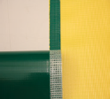
Uneven Fabric Tension
This is an example of too much tension held on the top fabric panel. It is important for the operator to hold even (equal) tension on both the top and bottom fabric panels as the machine is welding. As illustrated the green panel goes through the left side (top) of the welder and the yellow panel goes through the right side (bottom ) of the welder. When more tension is held on the top panel, the bottom panel will show wrinkling next to the weld. Adjust the tension held to give a smoother finish.

Uneven Fabric Tension
This is an example of too much tension held on the bottom fabric panel. It is important for the operator to hold even (equal) tension on both the top and bottom fabric panels as the machine is welding. As illustrated the green panel goes through the left side (top) of the welder and the yellow panel goes through the right side (bottom ) of the welder. When more tension is held on the bottom panel, the top panel will show wrinkling next to the weld. Adjust the tension held to give a smoother finish.

Perfect Seam
This is an example of a perfect seam. There is no waviness, wrinkles, or puckers. The heat, speed, and pressure, combined with the operators tension applied are perfect.
10.0 Maintenance
The Miller Weldmaster T3 has certain items that need maintained to keep the machine running as effectively as possible. The T3 has three chains that are used to drive the weld rollers and travel roller on the machine. Although not high maintenance items, chains should be inspected every 3 months
to ensure there is not excessive corrosion, rust, or dirt. Also inspect for any looseness in the chain, sprockets, or gears. If needed, lubricate chains and gears once every 3 months with 80-90w gear oil.
1. Before starting inspections or maintenance of any kind the power disconnect and air valve must be turned to the off position.
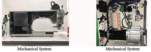
2. Remove the back cover of the machine and inspect the chains, sprockets, gears, and all other mechanical parts. During the inspection, look for wearing surfaces, dark dust under the sprockets and gears, dry chains, or any other signs of wear.
3. Oil chains, sprockets, and gears as needed. Replace worn out parts as needed.
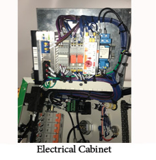
4. Once the mechanical system has been inspected and maintained then inspect the electrical system. Begin the inspection by first lightly blowing out the inside of the machine with a compressed air blow gun (be sure compressed air is completely dry and clean). Inspect electrical components, wire, and wire terminals for dark/discolored areas.
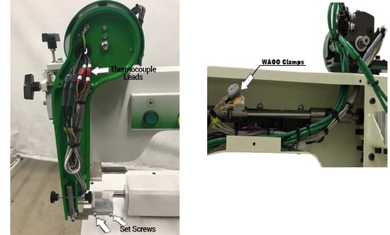
- Loosen and remove the housing cover.
- Disconnect the male from the female leads of the thermocouple.
- Disconnect the heater cartridge wires from the WAGO clamp.
- Loosen the two set screws located on the side of the wedge.
- Remove both bolts from the rear mounting bracket.
- Install the new wedge assembly reversing the above instructions
- When tightening the bolts onto the rear mounting bracket, loosen by a 1/8 of a turn so the wedge has some float in it.
6. Contact a Miller Weldmaster service representative with any questions or to discuss an area of uncertainty.
7. Once inspection and maintenance is complete, replace the back cover and tighten all mounting bolts.
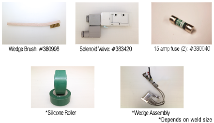
11.0 Recommended Replacement
Miller Weldmaster recommends keeping the following spare parts in stock:
NOTE: The manufacturer will not be held liable for any damage or injuries occurring from any inappropriate use of this machine.
12.0 Transportation and Storage
Transportation Within a Production Facility
Due to the weight of the Miller Weldmaster machine, the manufacturer requires two persons in order to move the machine. When lifting the machine grab hold of the base and not any insecure parts, also be sure to lift slowly and carefully to eliminate potential injury. Secure all components before lifting.
Transportation Outside a Production Facility
The manufacturer requires the Miller Weldmaster machine to be placed on a pallet and loaded into a truck using a forklift or tow motor. The forks are to be inserted below the bottom frame along the center of gravity. Before lifting the machine be sure to secure all components. Lift slowly to ensure proper placement of the forks. Secure the machine to the pallet or trailer and protect the various controls and features by crating the machine.
Storage
The manufacturer recommends that any time the machine is not in use, it must be protected from excess dust and moisture. The operator should familiarize themselves with the warning symbols on the machine to be alert to the potentially hazardous areas on the machine.
13.0 Additional Machine Documents